

A Story of Precision, Profit, and Prevention
In the heart of a bustling manufacturing facility, a single misplaced dimension on a technical drawing brought production to a grinding halt14. What started as a routine morning shift turned into a $150,000 nightmare when a machine operator discovered that 500 precision-machined components couldn’t fit their intended assembly2. The culprit? A missing decimal point in the engineering drawing that went unnoticed through multiple review cycles18. This isn’t just an isolated incident—it’s a stark reminder of why engineering drawing accuracy isn’t just about technical precision; it’s about protecting your organization’s bottom line, reputation, and future15.
The story of engineering drawings is fundamentally a story about communication, and like all communication, it’s fraught with opportunities for misunderstanding23. Every line, dimension, and symbol on a technical drawing carries the weight of intent from designer to manufacturer, from concept to reality32. When that communication breaks down, the consequences ripple through every aspect of production, from material waste and schedule delays to safety concerns and customer dissatisfaction21.
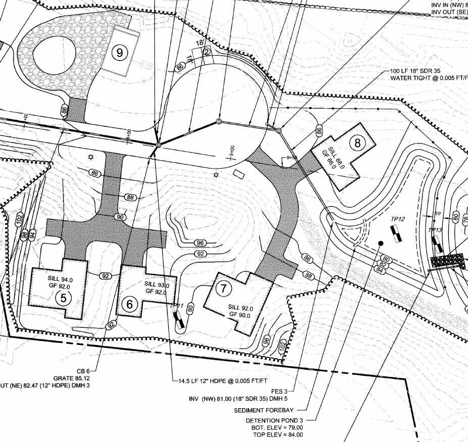
Example of a detailed technical engineering drawing or site planeci3d
The Hidden Cost of Drawing Errors: More Than Numbers on Paper
Recent industry analysis reveals that engineering drawing mistakes cost manufacturers up to 2.2% of annual revenue, with the worst performers facing costs that can cripple project budgets15. For a company generating $100 million annually, this translates to $2.2 million in preventable losses15. The most devastating aspect isn’t just the immediate financial impact—it’s the compounding effect of delays, reputation damage, and lost opportunities that follow4.
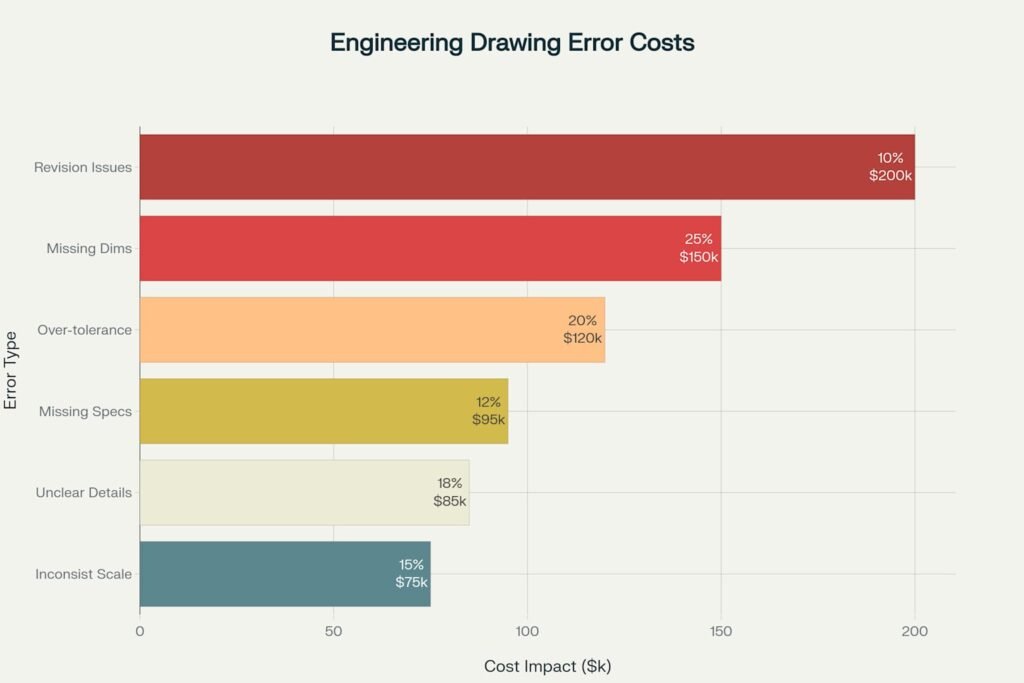
Cost Impact of Common Engineering Drawing Mistakes – showing both frequency and financial consequences
The data tells a sobering story about the most common and costly drawing errors plaguing modern manufacturing28. Missing dimensions account for 25% of all drawing-related errors, with each incident averaging $150,000 in direct costs2. Over-tolerancing follows closely at 20% of errors, often resulting from engineers’ conservative approach to specification, inadvertently driving up manufacturing costs by an average of $120,000 per incident7. The irony is palpable: in attempting to ensure quality through tighter tolerances, organizations often create quality problems through manufacturing complexity4.
Consider the case of a sheet metal manufacturer that discovered a drafting mistake only after producing 1,000 computer LCD covers8. The oversight—a failure to consider manufacturability during the design phase—added 15 seconds to each cover’s production time, ultimately costing the company $213,000 in additional labor and materials8. This real-world example underscores how seemingly minor oversights in drawing preparation can cascade into significant operational impacts8.
The Evolution of Drawing Standards: A Journey Toward Excellence
The transformation of engineering drawing standards over the past seven decades tells a remarkable story of continuous improvement and error reduction1116. Beginning with MIL-STD-8 in 1949, the industry has witnessed a systematic evolution toward more precise, standardized communication methods11.
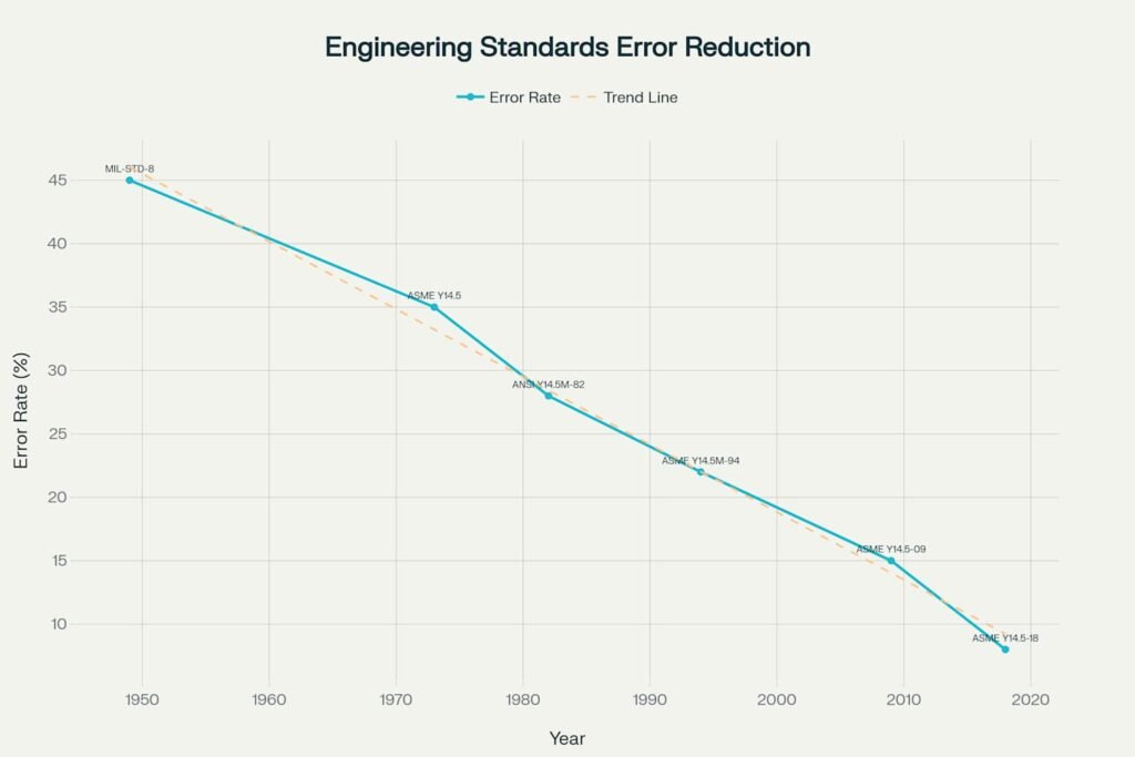
Evolution of Engineering Drawing Standards and Error Rate Reduction (1949-2018)
The introduction of ASME Y14.5 in 1973 marked a watershed moment in technical communication, establishing geometric dimensioning and tolerancing as a fundamental principle of design documentation1116. This standard didn’t merely provide guidelines—it created a universal language that transcended company boundaries and national borders10. The subsequent revisions in 1982, 1994, 2009, and 2018 each contributed to measurable improvements in drawing accuracy and manufacturing consistency11.
Today’s ASME Y14.5-2018 standard represents the culmination of nearly 70 years of refinement, incorporating digital product definition practices and model-based definition technologies1216. The standard’s 15 comprehensive sections cover everything from basic symbols and datums to complex tolerance applications, providing engineers with the tools necessary to communicate design intent with unprecedented clarity11.
The parallel development of ISO 128 standards has created global harmonization in technical drawing practices, ensuring that engineering drawings maintain consistency whether produced in Detroit, Dresden, or Delhi1317. These standards have evolved from simple line conventions to comprehensive frameworks addressing both manual and computer-based drawing creation13.
Part Drawing Checklist: The Foundation of Manufacturing Success
Creating accurate part drawings requires methodical attention to detail that goes far beyond simply documenting dimensions25. Each element of a part drawing serves a specific purpose in the manufacturing ecosystem, and omitting or incorrectly specifying any element can trigger costly downstream problems26.
Critical Drawing Elements
Cavity Number and Date Stamp Locations form the foundation of traceability in manufacturing operations25. For molded or cast parts, these seemingly minor details become crucial when quality issues arise months or years after production26. Aerospace and automotive industries particularly emphasize these requirements, as regulatory compliance often mandates complete traceability from raw material to finished component22.
Draft Angles and Manufacturing Considerations represent where design theory meets manufacturing reality5. The proper specification of draft angles can mean the difference between smooth production flow and costly tooling modifications9. Research in deep drawing processes demonstrates how improper angle specifications can create defects ranging from surface irregularities to complete part failure59.
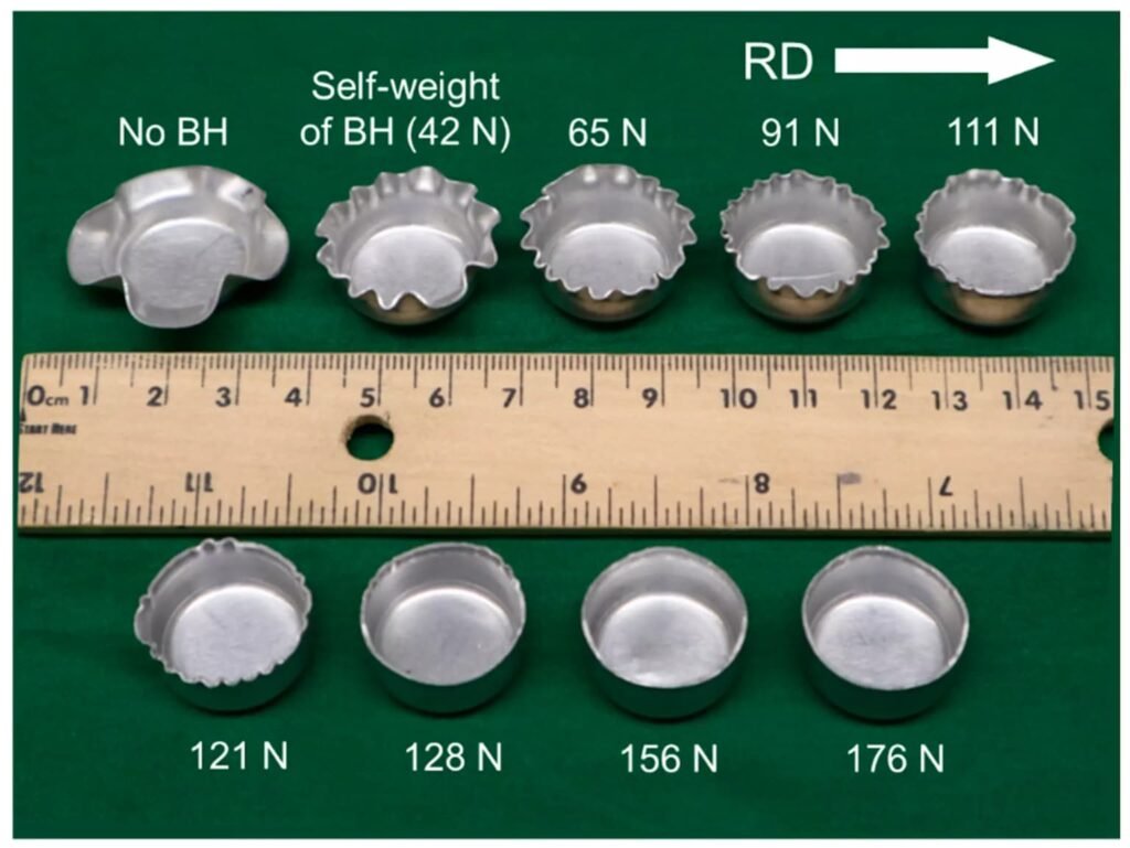
Deep drawing defects at various force levels measured in Newtonsems-metalworking
Material Specifications demand precision that extends beyond simple material names26. Modern manufacturing requires exact grade specifications, heat treatment requirements, and material property documentation25. A study of manufacturing defects found that material specification errors account for 12% of drawing-related problems, often resulting in parts that meet dimensional requirements but fail functional testing4.
Title Blocks and Documentation Standards serve as the central nervous system of drawing communication2532. These standardized information blocks contain project identifiers, approval signatures, revision histories, and critical notes that guide manufacturing decisions29. Australian construction standards, for example, mandate specific title block elements to ensure regulatory compliance and project coordination29.
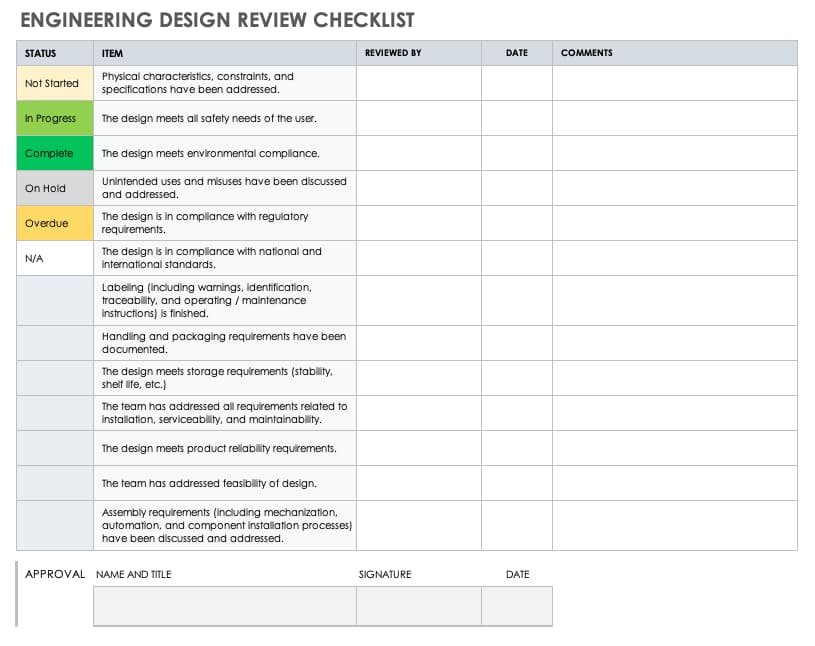
An example of an engineering design review checklistsmartsheet
Dimensional Control and Tolerancing
The art and science of dimensioning requires understanding both manufacturing capabilities and functional requirements7. Geometric dimensioning and tolerancing (GD&T) provides the framework for communicating these requirements, but improper application can create manufacturing nightmares7. Common errors include over-defining tolerances, creating conflicting dimensional controls, and failing to establish proper datum references7.
Revision Control Systems represent the backbone of engineering change management30. Proper revision tracking prevents the use of obsolete drawings while maintaining historical records of design evolution30. Digital tools now provide sophisticated version control capabilities, but the fundamental principles of change documentation remain critical30.
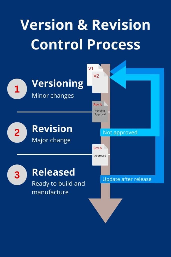
Diagram illustrating version and revision control processesopendomain
Assembly Drawing Checklist: Orchestrating Component Integration
Assembly drawings face unique challenges in communicating how individual components integrate into functional systems25. These drawings must balance comprehensive information with visual clarity, ensuring that assembly technicians can efficiently and accurately build complex products26.
Bill of Materials (BOM) Integration requires perfect synchronization between drawing annotations and parts lists25. Mismatches between balloon callouts and BOM entries can halt production while technicians seek clarification21. Leading manufacturers implement automated checking systems to verify BOM accuracy, reducing assembly errors by up to 60%22.
Special Materials and Processes demand explicit specification to prevent assembly errors26. Grease applications, adhesive placements, and torque requirements must be clearly documented with specific grades, quantities, and application procedures25. The aerospace industry has developed particularly stringent requirements for these specifications, recognizing their critical role in product reliability19.
Packaging and Handling Instructions often receive insufficient attention during drawing creation, yet they significantly impact product quality and customer satisfaction26. Proper packaging specifications prevent damage during shipping while ensuring that assembly instructions reach end users in usable condition25.
Drafting Standards and Best Practices: The Art of Technical Communication
Professional drafting transcends mere documentation—it represents the translation of complex three-dimensional concepts into two-dimensional instructions that must be universally understood28. This translation requires adherence to established conventions while maintaining clarity and completeness27.
Line Work and Visual Hierarchy
Dimension Line Management forms the foundation of readable drawings26. The cardinal rule that dimension lines must never cross each other isn’t arbitrary—it reflects decades of experience in manufacturing environments where clarity can prevent costly errors25. Extension lines should remain short and neat, creating visual pathways that guide the reader’s eye naturally through the drawing26.
View Selection and Arrangement requires strategic thinking about information presentation25. The goal is communicating maximum information with minimum visual complexity27. Experienced drafters spread views across the drawing sheet rather than cramming them together, creating breathing room that enhances comprehension26.
Modern CAD Integration
Template Standardization has become crucial as organizations embrace digital drafting tools28. Standard drawing templates ensure consistency across projects while reducing setup time for individual drawings27. University of Technology Sydney’s CAD standards exemplify this approach, mandating specific template usage and file naming conventions to maintain institutional consistency27.
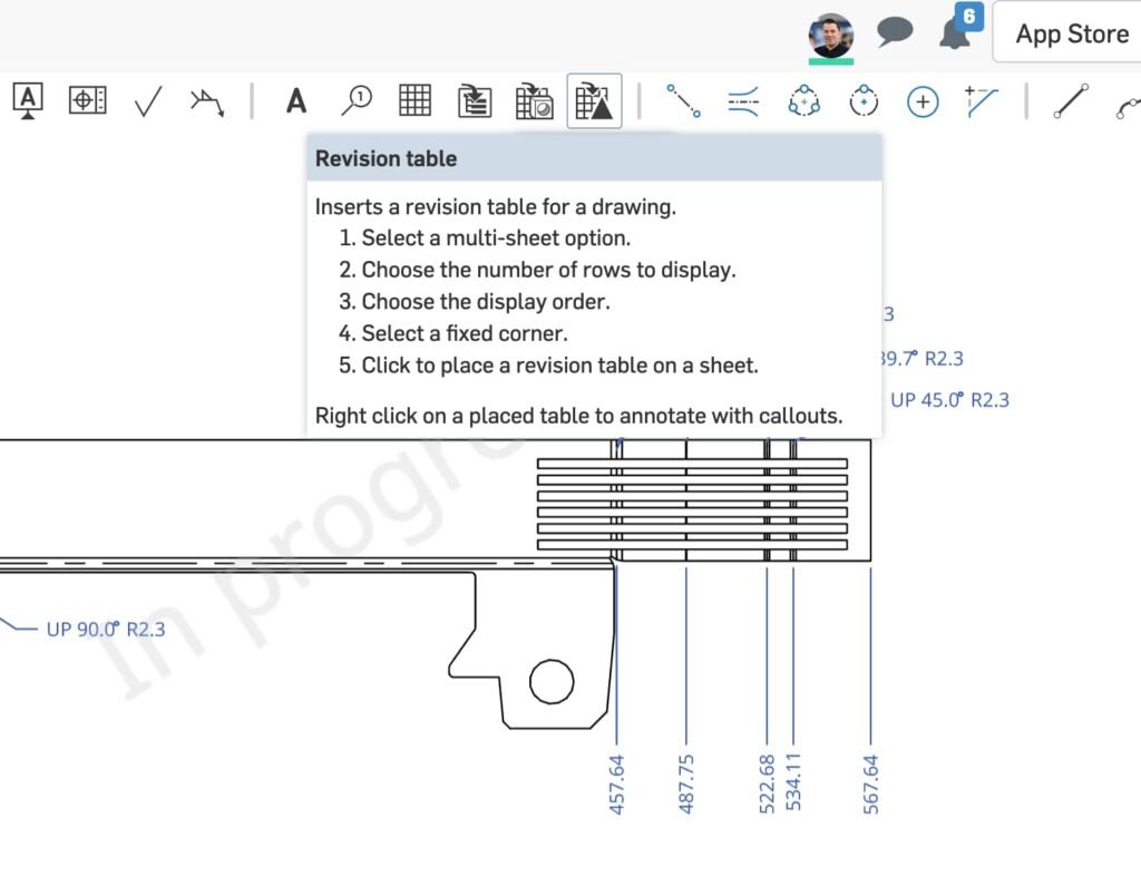
Inserting a revision table in CAD softwareonshape
Layer Management and File Organization represent critical aspects of modern drafting practice27. Proper layer usage facilitates drawing modification while maintaining visual organization28. Leading organizations implement comprehensive layer standards that support both current production needs and future modification requirements27.
The Business Case for Checklists: Quantifying Quality
The implementation of comprehensive drawing checklists delivers measurable benefits that extend far beyond error prevention22. Organizations that embrace systematic checking procedures typically experience transformational improvements in multiple operational areas15.
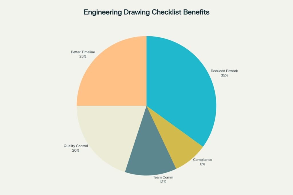
Key Benefits of Implementing Engineering Drawing Checklists – Distribution of organizational improvements
Cost Reduction represents the most immediately visible benefit of checklist implementation15. Companies implementing comprehensive drawing review procedures report 60-80% reductions in drawing-related errors, translating to millions of dollars in saved rework costs22. The automotive industry has documented particularly impressive results, with leading manufacturers reducing drawing-related production delays by 75%15.
Timeline Improvements emerge as teams develop proficiency with checking procedures22. While initial implementation may temporarily slow drawing release cycles, mature checklist processes actually accelerate project timelines by preventing downstream delays15. Manufacturing teams spend less time seeking drawing clarifications and more time on productive activities22.
Quality Enhancement manifests in both product reliability and customer satisfaction22. Consistent drawing quality creates predictable manufacturing outcomes, reducing variability in finished products15. This consistency builds confidence throughout the supply chain, from component suppliers to end customers22.
Implementation Strategy: From Concept to Culture
Successfully implementing engineering drawing checklists requires more than distributing forms—it demands cultural transformation that embraces systematic quality practices23. Organizations that achieve lasting success follow proven implementation strategies that address both technical and human factors22.
Implementation Tips for Engineering Drawing Checklists
Quick Start Guide
1. Establish Team Standards
- Designate a drawing standards champion in your organization
- Conduct monthly training sessions on drawing best practices
- Create a shared library of approved templates and symbols
2. Implement Progressive Checking
- Stage 1: Self-check by original drafter
- Stage 2: Peer review by another team member
- Stage 3: Final approval by senior engineer or project manager
3. Common Mistake Prevention
Based on industry data, focus extra attention on these high-risk areas:
- Missing dimensions (25% of all errors) – Use systematic dimensioning approach
- Over-tolerancing (20% of all errors) – Apply tolerance analysis principles
- Unclear details (18% of all errors) – Use standard notation and symbols
4. Technology Integration
- Implement CAD template standards across all projects
- Use automated checking tools where available
- Maintain version control with proper naming conventions
- Regular backup and archival procedures
5. Quality Metrics Tracking
Monitor these key performance indicators:
- Drawing error rate per project
- Time spent on drawing revisions
- Manufacturing rework due to drawing issues
- Client feedback on drawing clarity
6. Continuous Improvement
- Monthly drawing review sessions
- Feedback collection from manufacturing teams
- Regular updates to checklist based on lessons learned
- Industry standard compliance audits
Emergency Response Plan
When drawing errors are discovered:
- Immediate: Stop all work using the incorrect drawing
- Assessment: Determine scope of impact (materials, time, cost)
- Correction: Issue revised drawing with clear revision markings
- Communication: Notify all stakeholders immediately
- Analysis: Conduct root cause analysis to prevent recurrence
Success Metrics
Organizations implementing comprehensive drawing checklists typically see:
- 60-80% reduction in drawing-related errors
- 30-50% decrease in manufacturing rework
- 25-40% improvement in project timeline adherence
- Significant improvement in client satisfaction ratings
Resources for Continued Learning
- ASME Y14.5 Geometric Dimensioning and Tolerancing
- ISO 128 Technical Product Documentation
- Company-specific CAD standards documentation
- Professional development courses in technical drawing
Progressive Implementation prevents overwhelming teams while building competency gradually23. Beginning with critical projects or high-risk components allows organizations to refine procedures before full deployment22. This approach also creates success stories that build organizational support for broader implementation15.
Training and Development programs must address both technical skills and quality mindset23. Effective programs combine formal instruction with hands-on practice, allowing team members to develop proficiency in controlled environments22. Ongoing training ensures that teams stay current with evolving standards and best practices16.
Technology Integration leverages modern CAD capabilities to automate routine checking procedures28. Advanced systems can verify dimensional consistency, check material specifications, and validate drawing completeness automatically27. However, technology succeeds only when supported by solid procedural foundations30.
Metrics and Continuous Improvement provide the feedback mechanisms necessary for long-term success22. Key performance indicators should track both leading measures (checklist completion rates) and lagging measures (drawing error incidents)15. Regular review sessions allow teams to refine procedures based on real-world experience23.
Ultimate Engineering Drawing Checklist
| Category | Checklist Item | Priority | Checked | Comments |
|---|---|---|---|---|
| Part Drawing | Cavity number location specified (if applicable) | High | ||
| Part Drawing | Date stamp location specified (if applicable) | Medium | ||
| Part Drawing | Draft angles checked for molding/casting components | High | ||
| Part Drawing | Drawing template completely filled out | High | ||
| Part Drawing | Correct material grade/alloy specified | Critical | ||
| Part Drawing | Correct title with product description | High | ||
| Part Drawing | Date drawn included | Medium | ||
| Part Drawing | Sheet scale correctly displayed | High | ||
| Part Drawing | Latest updated details (drawn by/designed by) | Medium | ||
| Part Drawing | Third angle projection confirmed | High | ||
| Part Drawing | Revision block up to date | Critical | ||
| Part Drawing | Tapped holes with complete details | High | ||
| Part Drawing | Critical dimensions highlighted | Critical | ||
| Part Drawing | Company logo included on visible part | Medium | ||
| Part Drawing | Cavity numbers and logo details (raised/sunken) | Medium | ||
| Part Drawing | Material grade or alloy precisely specified | Critical | ||
| Part Drawing | Revision block history complete | High | ||
| Part Drawing | All dimensions in millimeters unless specified | High | ||
| Part Drawing | Tolerances specified per ASME Y14.5 standards | Critical | ||
| Part Drawing | Surface finish requirements clearly indicated | High | ||
| Assembly Drawing | BOM matches balloon annotations | Critical | ||
| Assembly Drawing | Grease details specified (grade, quantity, surfaces) | Medium | ||
| Assembly Drawing | Loctite details specified (grade, quantity, location) | Medium | ||
| Assembly Drawing | Title includes product and project numbers | High | ||
| Assembly Drawing | Kitting information included in BOM | Medium | ||
| Assembly Drawing | Packaging details specified | Medium | ||
| Assembly Drawing | Torque requirements specified for fasteners | High | ||
| Assembly Drawing | Assembly sequence clearly indicated | Medium | ||
| Assembly Drawing | Special handling instructions included | Medium | ||
| Assembly Drawing | Quality inspection points identified | High | ||
| Drafting Standards | Dimension lines do not cross each other | High |
Emergency Response: When Things Go Wrong
Even the most comprehensive checklist systems cannot prevent all errors, making emergency response procedures essential23. When drawing errors are discovered, rapid response can minimize damage while preserving stakeholder relationships21.
The immediate response must focus on containing the error’s impact23. This includes stopping work based on incorrect drawings, assessing the scope of affected materials and components, and communicating with all stakeholders21. Speed is crucial—delays in error communication compound both financial and relationship damage15.
Root cause analysis provides the foundation for preventing similar errors in the future22. Effective analysis examines not just the immediate error but the system conditions that allowed it to occur23. This broader perspective often reveals opportunities for process improvements that prevent entire categories of errors15.
Future Horizons: The Evolution Continues
The future of engineering drawing quality lies in the intersection of human expertise and technological capability16. Artificial intelligence and machine learning technologies promise to revolutionize error detection, potentially identifying problems that human reviewers might miss22. However, these tools will augment rather than replace human judgment, which remains essential for interpreting design intent and manufacturing feasibility23.
Model-based definition (MBD) represents another frontier in technical communication12. By embedding design information directly into three-dimensional models, MBD reduces the risk of translation errors while providing manufacturers with richer information for production planning16. This technology requires new approaches to quality control that extend beyond traditional drawing review12.
Digital twins and virtual manufacturing environments offer unprecedented opportunities for design validation19. These technologies allow engineers to test manufacturing processes virtually, identifying potential problems before physical production begins22. The integration of these capabilities with traditional drawing practices will create new paradigms for design communication and quality assurance15.
Conclusion: Building Excellence Through Systematic Practice
The journey toward engineering drawing excellence is not a destination but a continuous process of improvement and refinement14. Every drawing represents an opportunity to communicate design intent clearly, prevent manufacturing errors, and contribute to organizational success23. The checklist approach provides the framework for this excellence, but success depends on consistent application and continuous refinement22.
The stories of drawing errors and their consequences serve as powerful reminders of the stakes involved in technical communication21. Yet equally powerful are the success stories of organizations that have embraced systematic quality practices and reaped the rewards of reduced errors, improved efficiency, and enhanced customer satisfaction15.
As engineering practices continue evolving with new technologies and methodologies, the fundamental principles of clear communication, systematic verification, and continuous improvement will remain constant16. The ultimate design checklist for engineering drawings is not just a tool for error prevention—it’s a foundation for building organizational capability and competitive advantage in an increasingly complex manufacturing environment22.
The choice is clear: embrace systematic quality practices now, or face the mounting costs of drawing errors in an unforgiving marketplace15. The tools and knowledge exist to achieve excellence—the only remaining question is whether organizations will commit to the disciplined practice necessary to realize that potential23.
- https://www.reddit.com/r/MEPEngineering/comments/15mtzta/what_if_a_drawing_is_submitted_with_a_mistake/
- https://www.youtube.com/watch?v=L16Nx2_SUIU
- https://www.linkedin.com/pulse/10-common-construction-drawing-mistakes-cost-time-moneyand-anuj-r–bvbbf
- https://frigate.ai/cnc-machining/common-cnc-drawing-mistakes-that-increase-production-costs/
- https://ems-metalworking.com/deep-drawing-defects/
- https://www.estate.unsw.edu.au/sites/default/files/documents/Appendix%2010%20-%20UNSW%20Architectural%20CAD%20Standards%20Rev%201%20(Jan%202018).pdf
- https://www.gdandtbasics.com/avoiding-common-errors-in-gdt-drawings/
- https://www.hitechengineeringservices.com/blog/5-cad-drafting-drawing-mistakes-to-avoid/
- https://stampingsimulation.com/identifying-and-resolving-manufacturing-defects-through-detailed-simulation/
- http://alvarestech.com/temp/capp/GDT_Forma3D/Dimensioning%20and%20tolerancing%20engineering%20drawings%20and%20related%20documentation%20practices%20%20an%20international%20standard%20by%20American%20Society%20of%20Mechanical%20Engineers%20(z-lib.org).pdf
- https://en.wikipedia.org/wiki/ASME_Y14.5
- https://support.ptc.com/help/creo/creo_pma/r11.0/usascii/model-based_definition/rule_set.html
- https://en.wikipedia.org/wiki/ISO_128
- https://www.linkedin.com/pulse/importance-engineering-drawing-boopathi-soundararajan-ezx6c
- https://www.ease.io/blog/manufacturing-rework/
- https://blog.ansi.org/what-are-the-asme-y14-5-and-asme-y14-100-standards/
- https://cdn.standards.iteh.ai/samples/65296/94d88cd9fbd74672bdc3c842779c1232/ISO-128-1-2020.pdf
- https://www.youtube.com/watch?v=vLtohrTdboM
- https://news.mit.edu/2012/designing-for-failure-0615
- https://luukminkman.com/en/blog/car-drawing-mistakes/
- https://www.hkis.org.hk/ufiles/200712-ekam.pdf
- https://www.ptc.com/en/blogs/plm/quality-control-in-manufacturing
- https://www.linkedin.com/advice/0/how-can-you-ensure-your-engineering-drawings-wehze
- https://cardesign.jp/global/tips_only_cdastudents/car-sketches-lines.html
- https://www.mcgill.ca/engineeringdesign/step-step-design-process/basics-graphics-communication/drawing-format-and-elements
- https://www.tasnetworks.com.au/config/getattachment/411437d4-1b7b-41e9-9610-d1155052cb65/Drawing-Drafting-Standard-V3-Sep-2024.pdf
- https://www.uts.edu.au/cad-drawing-standards
- https://www.draftsight.com/media/drawing-standards
- https://alsyedconstruction.com/engineering-title-block-in-construction-in-australia-a-detailed-overview/
- https://us.caddi.com/resources/insights/drawing-revision-control
- https://cjtech.co.in/top-10-benefits-of-pdm-software/
- https://www.infrrd.ai/blog/title-block-engineering-drawing
- https://homeguide.com/costs/structural-engineer-cost
- https://www.asme.org/codes-standards/find-codes-standards/y14-5-dimensioning-tolerancing
- https://www.gdandtbasics.com/asme-y14-5-gdt-standard/
- https://www.reddit.com/r/MechanicalEngineering/comments/o0142u/poor_drawings_poor_design/
- https://waykenrm.com/blogs/engineering-drawing-overview/
- https://www.standards.org.au/documents/sa-simplified-drafting-template
- https://astcad.com.au/drafting-standards/


