Engineering support that gets manufacturing work moving.
Get help with CAD, tooling, manufacturing processes and engineering projects. See what KEVOS® can do, how an engagement works and what you can expect to receive.
From design and technical documentation to production improvement and project delivery, services are tailored to the work rather than a rigid package.
01
Engineering and CAD Support
Clear, accurate engineering documentation that production, suppliers and customers can work from. Suited to backlogs of drawing changes, products that need proper documentation, or designs that need to be made easier to manufacture.
Hands-on support to make production more repeatable: practical workholding and tooling concepts, layouts that suit the work, and instructions people can follow on the floor.
A structured look at how work actually flows, where time and effort are lost, and what practical changes would make the operation more stable and easier to run.
Practical support to get engineering projects defined, documented and delivered, from the first scope through to commissioning paperwork and close-out.
KEVOS® Engineering Problem Assessment and Factory Fix
Introductory fixed-scope service
Engineering Problem Assessment
A$195 Fixed-price remote assessment
A fixed-price remote review of one defined engineering or manufacturing problem: a 30-minute technical discussion, a preliminary review of the information you supply, up to three improvement options and a one-page written recommendation.
One defined problem, assessed remotely. Payment is requested only after the scope is confirmed. GST applies where applicable. The exact amount payable is confirmed in writing before you pay.
01Problem understanding
02Technical discussion
03Preliminary technical review
04Improvement options
05Written recommendation
Flagship offer
KEVOS® Factory Fix
From A$990
A focused engineering or manufacturing improvement engagement for businesses with one defined production, workflow, documentation or engineering problem that needs to be moved forward.
Package pricing is indicative only and depends on scope, complexity, site requirements and deliverables. The Engineering Problem Assessment is a fixed A$195 for one defined problem. GST applies where applicable.
04How it works
Clear scope first. Then the work.
Every engagement follows a straightforward process so the scope, timing and costs are discussed before substantial work begins.
01
Tell us the problem
Describe the job, the problem or the project. Drawings, photos and a short explanation are usually enough to start the conversation.
02
Scope the work
KEVOS® defines the scope, deliverables, assumptions, timing and commercial terms in writing before substantial work begins.
03
Complete the engineering work
The agreed work is carried out, with check-ins at sensible points so questions are answered early rather than at the end.
04
Deliver and close out
Deliverables are handed over in agreed formats, questions are answered and the work is closed out cleanly.
What is confirmed before work begins
Scope
What is included and what is outside the agreed assignment.
Deliverables
The models, drawings, documents or plans you will receive and their formats.
Assumptions
The information, site access and decisions the work relies on.
Timing
Starting points, check-ins and expected completion.
Commercial terms
Price or rate, how variations are handled and invoicing arrangements.
Ways to engage
Fixed-price proposals
Encouraged for suitable small assignments with a clear scope and defined deliverables.
Staged discovery
For problems that are not yet well defined: a short first stage clarifies the problem before the main work is quoted.
Day rate or time-based work
For flexible or evolving tasks where the scope is hard to fix in advance.
Monthly support
Ongoing engineering and documentation support on an agreed monthly arrangement.
Package pricing is indicative only and depends on scope, complexity, site requirements and deliverables. The Engineering Problem Assessment is a fixed A$195 for one defined problem. GST applies where applicable.
What to send with an enquiry
A short description is enough to start; only share material you have permission to provide.
A short explanation of the problem or project and the result you want
Any available drawings, models, photos or relevant documents
Important deadlines, site constraints and access considerations
KEVOS® starts with the manufacturing problem. Similar design, documentation and process challenges appear in many production environments.
Manufacturing
Production processes, documentation, tooling and flow for general manufacturers.
Fabrication
Drawings, fixtures and workflow for metal and other fabrication businesses.
Industrial equipment
Engineering documentation and project support for equipment builders and suppliers.
Building-product manufacturing
Process, documentation and production support for building-product makers.
Plastics and components
Documentation, tooling concepts and process support for component producers.
Assembly operations
Work instructions, layouts and standardisation for assembly work.
Small and medium OEMs
Engineering capability without adding permanent engineering headcount.
Production businesses
Practical improvement for businesses that make things every day.
Engineering suppliers
Drawings, RFQ documentation and project support for suppliers to industry.
The problems matter more than the sector
Documentation gaps
Out-of-date or missing drawings that leave production relying on memory or constant clarification.
Unstable processes
Jobs that run differently depending on who is working, leading to rework or inconsistent quality.
Production bottlenecks
A single process, approval or machine holding up the rest of the operation.
Setup and handling waste
Time lost to repeated setups, double handling or poor workholding.
Projects without bandwidth
Technical improvements that matter but lack enough engineering time to get moving.
Knowledge held by one person
Critical know-how that should be captured in clear procedures and work instructions.
Sydney and NSW businesses, with suitable remote engineering and documentation support available elsewhere in Australia.
06About KEVOS®
Practical expertise, from the floor up.
KEVOS® is a small engineering-led business set up for defined technical assignments without the overhead of another permanent engineering position.
Its founder's background runs from making components through design, product development, operations improvement and project delivery. That helps connect drawings, tooling, processes, people and documentation.
Look at the actual job, process, drawing or bottleneck before proposing a fix.
02
Practical over theoretical
Solutions should work on the floor and be maintainable by the people who use them.
03
Clear scope, no surprises
Scope, deliverables, assumptions and commercial terms are agreed before substantial work starts.
04
Document it properly
Work should be understandable, checkable and reusable after the engagement ends.
05
Respect confidentiality
Client drawings, data and information are used only for the agreed work.
06
Be honest about limits
Where certified, registered or specialist input is required, KEVOS® says so.
Professionally equipped for commercial work
KEVOS® uses commercially licensed engineering and productivity software for professional client work, including licensed SolidWorks/CAD software and Microsoft Office productivity tools, to produce client-ready engineering and project documentation.
Licensed SolidWorks/CAD software
Microsoft Office-compatible deliverables
Client-ready drawings and documentation
SOLIDWORKS is a registered trademark of Dassault Systèmes or its subsidiaries. Microsoft, Microsoft 365 and Office are trademarks of the Microsoft group of companies. KEVOS® is not affiliated with, endorsed by or a partner of these companies.
Client drawings, data and information are used only for agreed work. Some statutory approvals or professional certification require appropriately qualified specialists. KEVOS® does not share confidential information from previous employers, clients or suppliers. Read the disclaimer.
07READOS and WORKOS
Read, learn and put ideas to work.
Explore books and guides with READOS. Use WORKOS calculators and decision tools to work through costs, plans and practical choices.
READOS. Find a subject, open a book and follow its chapters. Animated pages turn in an open book.
An approachable, practical guide to reading financial statements, interpreting cash flow, assessing business quality, and asking better valuation questions.
From steelworks to medical devices: 40 Australian engineering projects worth sharing.
The engineering record behind KEVOS®, built since 2010 on a career that started on the toolroom floor. Coke plants, mine-site trucks, production machinery, window and door hardware taken from 3D print to production, rail interiors, bridges, food plants and patient-specific devices, carried out by its founder in employed, contract and consulting roles. Each record shows where the work happened, the role, what was delivered and, honestly, how far it went.
Project records
40
Years
2010–2026
Sectors
8
Named organisations
16
No projects match that search. Try a broader word, or .
Illustrative
2026Capital projectsFeatured
Two ultrasonic stripping lines, from contractor scopes to handover
Dual-line ultrasonic jig-stripping facility
Alchin Long Group · Building-hardware manufacturing · Sydney, NSW
A capital installation of two ultrasonic stripping and wash lines, with gantries, hoists and segregated chemical transfer, taken from contractor scopes to handover.
Commissioned and handed over
Capital project delivery
Contractor scoping
Chemical transfer
Executive cost reporting
Read the full case study
Illustrative
Illustrative KEVOS® visual. Not an image of the actual project, product, drawing or CAD.
Employment contextExperience of the founder of KEVOS®, gained while employed by Alchin Long Group as Operations Excellence Engineer (from November 2024). It is professional track record, not a KEVOS® client engagement.
The brief
Production jigs collect coating build-up and must be stripped clean to stay in service. The business invested in a dedicated facility: two ultrasonic stripping and wash lines, lifting equipment to move jig loads between tanks, and chemical transfer that keeps incompatible chemistries apart. It had to be installed safely around live production, through specialist trades, within an approved capital budget, while other capital, tooling and maintenance work drew on the same toolroom, contractors and production windows.
How the work was approached
Scopes before quotes
Contractor scopes were defined for the stripping and pressure-wash tanks, the gantry, hoists and trolleys, chemical transfer and services, so quotations could be compared like for like.
Options tested on paper
Pump options for chemical transfer were assessed for duty, safety and maintenance, and air-operated double-diaphragm (AODD) pumps were procured for the duty.
Segregation and lifting designed in
Chemical transfer was kept segregated, chemical containers were given bunded storage, and the gantry, hoists and trolleys were specified to move jig loads safely between the stripping and wash stages.
Specialist trades coordinated
Electrical work for the tanks and hoists, pneumatic and plumbing modifications and specialist installers were sequenced around production. Hoist limit switches, wiring and strikers were installed so hoist travel was controlled before commissioning.
When every project needs the same toolroom
The facility sat in one register with the other active capital, tooling and maintenance work, each tracked by owner, stage, cost, main risk, dependencies and next action. Clashes over trades, contractors and production windows were raised early with costed options, so management could set priorities on safety, production impact and urgency.
Cost visible to the executive
Approved allocation was compared with committed, actual and forecast cost and reported to the executive team, because a raised purchase order is future spend before any invoice arrives.
Outcome
Two ultrasonic stripping and wash lines were installed, commissioned and handed over to production, with cost reported against the approved allocation throughout.
Why it mattersClear scopes and visible cost keep a multi-trade capital project under control from the first quote to handover.
Commercial figures are not shown. Investment decisions and approvals sat with management.
Illustrative
2026Capital projects
Custom colours on glass-filled plastic, proven for production
Custom-colour powdercoating of glass-filled plastic
Alchin Long Group · Building-hardware manufacturing · Sydney, NSW
Specialised process development to powdercoat a Tier 1 range of glass-filled plastic parts in custom colours, from first trials to a validated production finish.
Process validated
Process development
Powder coating
Production jigs
Project governance
Read the full case study
Illustrative
Illustrative KEVOS® visual. Not an image of the actual project, product, drawing or CAD.
Employment contextExperience of the founder of KEVOS®, gained while employed by Alchin Long Group as Operations Excellence Engineer (from November 2024). It is professional track record, not a KEVOS® client engagement.
The brief
Powdercoating glass-filled plastic in custom colours is not routine: the substrate, the finish and the jigging all have to be proven. A Tier 1 product range needed a repeatable process, a large set of purpose-made production jigs and clear project governance, delivered with internal resources while its jigs competed for the same toolroom as drill jigs, product modifications, maintenance and urgent production work.
How the work was approached
Coating trials
Trials established how the glass-filled plastic substrate accepted custom-colour finishes.
Parameters locked in
Operating parameters were set up and documented so the finish could be repeated run after run.
Finish validated
Finish quality was validated against the requirements of the Tier 1 range before release.
Jigs at production scale
Around 350 purpose-made production jigs were coordinated so parts could be coated consistently at volume.
Make or buy, decided on the schedule
Where repeat jigs could be made externally while internal development continued, the schedule benefit was set against the extra unit cost so management could decide quickly.
Governed with internal resources
The project ran with internal teams under clear governance, with short updates on status, cost position, the main risk and any decision needed. In-house labour stayed well inside the project allocation.
Outcome
A validated custom-colour powdercoating process for the Tier 1 range, delivered with in-house labour well inside its project allocation.
Why it mattersA proven, documented process turns a difficult finish into a repeatable product offer.
Commercial figures and customer details are not shown.
Illustrative
2024–2025Capital projectsFeatured
Two louvre production lines, from layout to handover
Single- and double-louvre manufacturing lines
Alchin Long Group · Building-hardware manufacturing · Sydney, NSW
New single- and double-louvre production lines taken through layout, equipment, contractor works, trials and qualification to a production handover with standard work in place.
Handed over to production
Production line setup
Equipment qualification
ERP routing
Lean implementation
Read the full case study
Illustrative
Illustrative KEVOS® visual. Not an image of the actual project, product, drawing or CAD.
Employment contextExperience of the founder of KEVOS®, gained while employed by Alchin Long Group as Operations Excellence Engineer (from November 2024). It is professional track record, not a KEVOS® client engagement.
The brief
Bringing louvre manufacturing into production meant more than installing equipment. The lines needed a workable layout, coordinated contractor works, trials and qualification, and the business systems, standard work and trained operators to run them well from the first shift, all while sharing the toolroom, contractors and production windows with other projects running at the same time.
How the work was approached
Layout and equipment
Line layouts and equipment were coordinated for single- and double-louvre production, with contractor works scheduled around the factory.
Trials and qualification
The lines were trialled and qualified against controlled equipment-qualification documents and machine instructions before release.
Systems ready on day one
ERP parts, kit and routing requirements were defined for the systems team, so orders, materials and costs flowed from the first production run.
One plan for shared resources
Line works were tracked in a common register alongside the other active projects, with milestones, actions and dependencies followed up across engineering, the toolroom, purchasing, production and contractors.
Lean from the start
Standard work, operator training, Kanban and value-stream mapping were introduced with the lines, and product costing was supported with time-study data.
Closed out properly
Before handover, scope, outstanding actions, documentation and operator training were confirmed, and ownership passed to the production team.
Outcome
Both louvre lines were qualified and handed over to production with standard work, trained operators and system data in place.
Why it mattersLines that start with standard work, trained people and correct system data reach stable output sooner.
Illustrative
2024Window and door hardware
Retooling the base of a twin chainwinder, proven over two test rounds
Doric DN450 twin chainwinder base retool
Alchin Long Group · Doric · Window and door hardware · Sydney, NSW
A retool of the base of the existing Doric DN450 twin chainwinder: design update, new tooling, and two rounds of off-tool testing either side of a tooling correction, approved by the customer in November 2024.
Customer approved
Retooling
Tooling coordination
Off-tool testing
Design for manufacture
Read the full case study
Illustrative
Illustrative KEVOS® visual. Not an image of the actual project, product, drawing or CAD.
Employment contextProduct-development experience of the founder of KEVOS®, gained while employed by Alchin Long Group as Design Drafter and Product Development (May 2018 to October 2024). It is professional track record, not a KEVOS® client engagement.
The brief
The DN450 twin chainwinder was already an established product. This work covered its base: the part was updated where needed and retooled, and the new tool had to produce bases that fitted the assembly and matched the approved design. It was a retool of one component, not the design of the whole DN450.
Objectives
Update the base design for the new tool
Prove the change in CAD, a working prototype and drawings before tooling
Test off-tool bases, correct the tool and test again
Reach customer approval on the new tool
Role in the work
As Design Drafter and Product Development, the founder’s contribution covered:
Rapid CAD modelling and 3D-printed prototypes
Detailed CAD models and CNC working prototypes
Technical drawings and bills of materials
Tooling quotations and tooling coordination
Off-tool sample testing and tooling corrections
Final testing and samples for customer approval
How the work was approached
Design and prototype
A detailed CAD model and CNC working prototype were completed in January 2024, with technical drawings and the BOM in February.
Tooling approved
The tooling quotation was reviewed and the tooling and testing plan approved in March 2024.
A new tool
The new tool was made between March and August 2024, and the production meeting followed in September.
Test, correct, re-test
Off-tool bases were tested in September, the tool was corrected through to mid-October, and a second round of off-tool testing followed.
Final testing and approval
Final testing was completed in early November, and the customer approved the retooled base in November 2024.
Development path
Jan–Mar 2024Design
CAD model and CNC prototype, drawings and BOM, tooling quotation and plan approved
Mar–Aug 2024Tooling
New tool made; production meeting in September
Sep–Oct 2024Test and correct
Off-tool testing, tooling corrections, second off-tool round
Nov 2024Approval
Final testing and customer approval
Challenges and how they were handled
The first off-tool bases needed correction.
The tool was corrected and a second round of off-tool testing was run before final testing, so approval rested on parts from the corrected tool.
Testing and validation
Two rounds of off-tool testing either side of the tooling correction, then final testing before customer approval in November 2024.
Outcome
The retooled DN450 base was approved by the customer in November 2024. The project schedule ends at customer approval, so production release is not claimed here.
Why it mattersRe-testing after every tool correction is the difference between a fixed tool and a hopeful one.
In the company’s development process, briefs, prototype approval and customer approval sat with product management; quotation review, ordering and freight sat with supply; and final testing was shared with quality. Dates come from the project schedule. Drawings, CAD models, tooling details, supplier information and internal project records are not shown.
Illustrative
2024Window and door hardware
An existing twin chainwinder housing, improved and retooled in four months
DN400 twin chainwinder housing upgrade
Alchin Long Group · Window and door hardware · Sydney, NSW
An engineering improvement to the housing of an existing twin chainwinder: new tooling, off-tool inspection with extra test samples, tooling corrections and customer approval in July 2024.
Customer approved
Product improvement
Tooling coordination
Off-tool inspection
Design for manufacture
Read the full case study
Illustrative
Illustrative KEVOS® visual. Not an image of the actual project, product, drawing or CAD.
Employment contextProduct-development experience of the founder of KEVOS®, gained while employed by Alchin Long Group as Design Drafter and Product Development (May 2018 to October 2024). It is professional track record, not a KEVOS® client engagement.
The brief
Improving a product already in the market is different from designing a new one. The change has to suit the existing assembly, and the tooling has to deliver it consistently. For the DN400 twin chainwinder housing, the design stages were already recorded as complete when the tracked program began in March 2024, so the work concentrated on tooling, inspection, testing and corrections.
Objectives
Carry the housing improvement into production tooling
Inspect off-tool parts and test enough samples to judge them
Correct the tooling and complete final testing
Reach customer approval for the improved housing
Role in the work
As Design Drafter and Product Development, the founder’s contribution covered:
Rapid CAD modelling and 3D-printed prototypes
Detailed CAD models and CNC working prototypes
Technical drawings and bills of materials
Tooling quotations and tooling coordination
Off-tool sample testing and tooling corrections
Final testing and samples for customer approval
How the work was approached
Ready for tooling
The concept, development and tooling-quotation stages were recorded as complete when the program began in March 2024, and the tooling and testing plan was approved straight away.
New tooling
Tooling was made between March and May 2024.
Inspection and more samples
Off-tool parts were inspected in May and June 2024, and additional samples were requested for testing.
Corrections and approval
After off-tool testing in June, the tooling was corrected in July, and final testing and customer approval were completed in late July 2024.
Development path
Recorded Mar 2024Design
Concept, development and tooling-quotation stages complete; tooling plan approved
Mar–May 2024Tooling
Tooling made
May–Jun 2024Inspect and test
Off-tool inspection, extra samples requested, testing
Jul 2024Correct and approve
Tooling corrections, final testing, customer approval
Challenges and how they were handled
Too few samples to judge the first off-tool parts.
Additional samples were requested before testing, so the corrections that followed were based on a larger set of parts.
Testing and validation
Off-tool inspection, testing on additional samples, tooling corrections and final testing before customer approval in July 2024.
Outcome
The improved DN400 housing was approved by the customer in July 2024. The project schedule ends at customer approval, so production release is not claimed here.
Why it mattersTesting enough off-tool samples before correcting a tool avoids chasing the variation of a single part.
In the company’s development process, briefs, prototype approval and customer approval sat with product management; quotation review, ordering and freight sat with supply; and final testing was shared with quality. Dates come from the project schedule. Drawings, CAD models, tooling details, supplier information and internal project records are not shown.
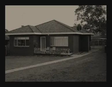
2024Civil and structural
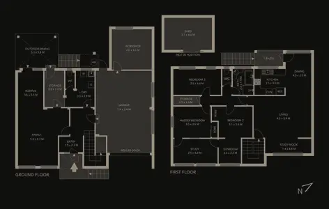
One drawing package a builder could build from
Residential development documentation
Residential builder · Residential construction · Girraween, NSW
Turned a builder’s requirements into one coordinated drawing package for approval and construction.
Documentation delivered
Design coordination
Buildability
Compliance awareness
Stakeholder communication
Read the full case study
Image from the published project record, converted to KEVOS® colours.
The brief
The builder needed a complete CAD documentation package for a new home. Site conditions, planning requirements, relevant Australian Standards and construction practicality all had to be reflected, and the package had to stay consistent as revisions came through.
How the work was approached
Site and intent first
Site information and the builder’s intended outcome were reviewed before drawing began.
Coordinated drawings
Site and layout plans, floor plans, elevations and construction details were developed as one coordinated package.
Structure integrated
Structural information was incorporated so architectural intent and structural requirements matched across every sheet.
Revisions under control
Changes were worked through directly with the builder and carried across every affected drawing.
Outcome
A structured technical reference that let the builder progress the development through approval and construction.
Why it mattersConsistent drawings mean fewer questions on site and fewer surprises at approval.
Engineering certification and statutory approval remained with registered professionals.
2024Plant and facilities
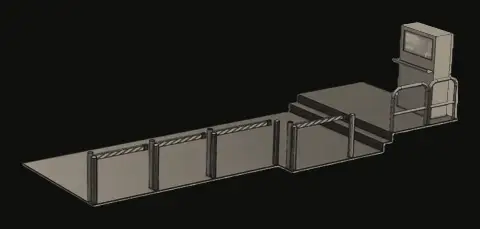
Separating people from forklifts on a busy plant floor
Plant access control and traffic separation
Pet food manufacturer · Food manufacturing
Boom-gate access control and layout changes to separate forklifts, vehicles and pedestrians on an active site.
Design stage
Plant layout
Traffic separation
Access control
Safety by design
Read the full case study
Image from the published project record, converted to KEVOS® colours.
The brief
Forklifts, pedestrians, maintenance staff and vehicles shared the same areas, creating points where different traffic could meet. The task was broader than choosing a boom gate: the plant needed controlled access and clear movement routes that still let production and maintenance work efficiently.
How the work was approached
How the area really works
Site conditions, access points, equipment locations and the movement of forklifts, staff and maintenance personnel were reviewed to find the real conflict points.
Access control in context
An automated boom-gate concept was positioned within the wider layout, considering controlled entry, sensing and warning, and access-authorisation options.
Traffic separation
The layout was revised to separate pedestrian routes, forklift movement and maintenance access zones.
Staged implementation
Changes were planned in modular stages so improvements could be introduced while manufacturing continued.
Outcome
A structured design response that treated layout, access, pedestrian safety and traffic control as one system. It remained at design stage and was not taken to fabrication or installation.
Why it mattersEngineering controls and clear routes reduce reliance on everyone always doing the right thing in a busy area.
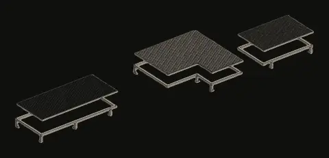
2024Plant and facilities
Safe maintenance access, designed for a hygiene-critical floor
Stainless-steel maintenance access platform
Food manufacturer · Food manufacturing
A hygienic stainless-steel platform giving safe maintenance access to equipment in an operating food plant.
Not progressed by client
Hygienic design
Maintenance access
Safety by design
3D CAD
Read the full case study
Image from the published project record, converted to KEVOS® colours.
The brief
Maintenance staff needed better access to equipment in a hygiene-sensitive production area. Any structure had to work around existing equipment, cleaning requirements, people movement and live production, while staying practical to fabricate and install.
How the work was approached
Site assessment
The plant arrangement, clearances and maintenance tasks were reviewed to fix where the platform could go and how people would use it.
Stainless-steel design
Members, walking surfaces, access, egress and edge protection were developed as a stable stainless-steel structure suited to regular cleaning.
Hygiene by design
Material choice, surface configuration and cleaning access were treated as design requirements alongside structure.
Review and buildability
A detailed 3D model supported stakeholder review, and a modular approach allowed fabrication and installation in manageable sections.
Outcome
A defined design for safer maintenance access in a hygiene-sensitive area. The client did not proceed to construction.
Why it mattersAccess, hygiene, safety and buildability were resolved together rather than traded off on site.
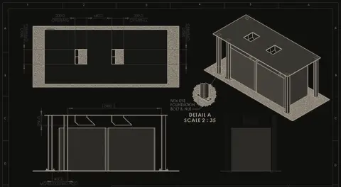
2024Plant and facilities
Heavy-duty bin handling, designed to grow with production
Bin collection and materials-handling structure
Food manufacturer · Food manufacturing
An engineering proposal for a high-volume bin collection system, designed to fit an existing production area and allow future expansion.
Paused by client
Structural design
Materials handling
Constructability
Risk management
Read the full case study
Image from the published project record, converted to KEVOS® colours.
The brief
A major food-manufacturing project needed a bin collection system that could handle high-volume material movement inside an active facility. Structure, throughput, plant integration, safety, constructability, sequencing, cost and future expansion all had to be balanced, with minimal disruption to production.
How the work was approached
Requirements and loads
Site conditions, expected loads, production requirements and surrounding infrastructure set the basis for the design.
Structure and material flow
The structural concept was developed together with how material would move through the system and interact with production.
Modular and scalable
A modular arrangement allowed future capacity to be added and made fabrication, transport and installation more practical.
Built with the contractor
Constructability, installation sequence, cost and risk were reviewed with the primary contractor before implementation.
Outcome
A defined engineering proposal ready for implementation. The end client paused the project after a change in internal strategy, before construction.
Why it mattersDesigning for expansion early avoids replacing a structure when production grows.
2023Machines and automation
Capturing critical tooling knowledge before it walks out the door
Reverse engineering and automation for blow-moulding tooling
Australian manufacturer · Food-related blow moulding
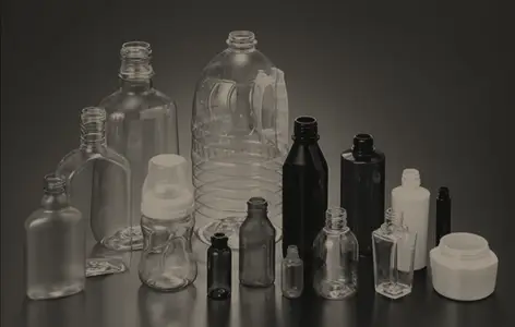
Documented critical tooling components through reverse engineering and developed a pick-and-place automation concept for the process.
Design delivered
Reverse engineering
Automation concepts
Manufacturing drawings
Process improvement
Read the full case study
Image from the published project record, converted to KEVOS® colours.
The brief
Two problems sat side by side. Critical tooling components were hard to reproduce because complete manufacturing information did not exist, and a repetitive manual handling task limited process consistency. Both needed practical engineering answers suited to a food-related production environment.
How the work was approached
Reverse engineering
Existing components and reference information were used to rebuild each part digitally, with critical dimensions and features defined in parametric 3D models.
Drawings for manufacture
The models became manufacturing drawings and technical documentation, with feasibility reviewed so the parts could be made and managed through normal processes.
Automation concept
The manual handling task was reviewed and a pick-and-place concept developed, considering equipment layout and integration with the existing process.
Hygiene and feedback
Food-production and hygiene requirements were considered throughout, and the design was refined with technical and operational feedback.
Outcome
Critical components became documented and repeatable to manufacture, reducing reliance on undocumented knowledge. The automation study set out a practical path to less repetitive manual handling and more consistent processing.
Why it mattersDocumented tooling can be quoted, made and replaced by any capable supplier, not only by the person who remembers how.
2023Plant and facilities
Designing the hazard out of hopper maintenance
Hopper maintenance access and safety redesign
Food manufacturer · Food manufacturing
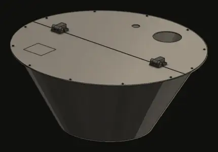
A modular hopper-cover concept that protects maintenance staff and makes access easier on a high-volume line.
Concept design
Safety by design
Maintenance engineering
Problem definition
Plant integration
Read the full case study
Image from the published project record, converted to KEVOS® colours.
The brief
Maintenance staff working around a hopper faced falling debris, restricted access, potential pinch points and awkward working positions. A better cover had to protect people without making the equipment harder to service, clean or run.
How the work was approached
Learn from the people doing the work
Site assessment and discussion with maintenance personnel showed where access was needed, what was serviced regularly and where the risks were.
Modular protection
A cover with detachable sections let specific areas be opened for maintenance without removing the whole assembly.
Safety designed in
Physical protection, access and provision for safety interlocking with machine shutdown controls were considered from the start.
Built for the environment
Materials were considered for dust, moisture, cleaning, vibration and repeated access, and the design was fitted around the existing plant in 3D.
Outcome
A practical concept for better protection and maintenance access. It remained at concept stage and was not taken to fabrication or installation.
Why it mattersGood guarding protects people and keeps maintenance quick, so nobody is tempted to work around it.
2023Plant and facilities
Re-planning a working factory for a hydrogen-ready future
Plant layout and hydrogen-readiness planning
Liquip International · Bulk liquid equipment manufacturing
An updated factory layout and documentation for planning future plant changes, including hydrogen-related infrastructure.
Layout delivered
Plant layout
Brownfield engineering
Equipment integration
Future planning
Read the full case study
Image from the published project record, converted to KEVOS® colours.
The brief
Liquip needed to plan changes to its manufacturing facility, including room for future hydrogen-related infrastructure. Changes had to fit around existing machinery, utilities, access routes and material flow without disrupting production.
How the work was approached
Existing plant captured
The factory footprint and equipment arrangement were reviewed and represented accurately as the basis for any change.
Layout options
Coordinated CAD layouts explored proposed changes in terms of equipment, working areas and manufacturing flow.
Interfaces checked
Equipment, access, services and workflow interactions were reviewed digitally before anything moved on the floor.
Future-ready planning
Space and arrangement were considered for future hydrogen-related infrastructure as part of Liquip’s hydrogen-readiness program.
Outcome
A coordinated layout and documentation basis for reviewing future modifications to the facility.
Why it mattersTesting layout changes on screen is far cheaper than moving machines twice.
Specialist hydrogen-system design remained with appropriately qualified specialists.
2023Product development
Designing a therapy device to cost less to make
Percussive therapy device
Sydney-based physiotherapist · Health and wellness products · Sydney, NSW
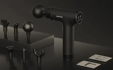
A lower-cost percussive therapy device, taken from the client’s idea to a 3D product design.
Not progressed by client
New product development
Design simplification
Cost engineering
3D visualisation
Read the full case study
Image from the published project record, converted to KEVOS® colours.
The brief
The client saw an opportunity for a percussive therapy product that delivered the needed function while being simpler and cheaper to manufacture than existing options. Function, simplicity, ergonomics, appearance, assembly and production cost had to be balanced from the start.
How the work was approached
Requirements before CAD
The intended product, user and operating concept were turned into structured requirements, separating essential features from nice-to-haves.
Concepts and sketches
Alternative configurations were sketched and compared before committing to detailed geometry.
Simplify the architecture
Functions were consolidated and part count reduced, because every component adds cost, assembly time and quality risk.
Model, visualise, refine
The product was developed in 3D CAD with attention to ergonomics and a wellness-oriented look, and refined through client reviews.
Outcome
A developed product design ready for prototyping. The client chose not to take it into commercial production.
Why it mattersCost is cheapest to remove at concept stage, before tooling and suppliers lock it in.
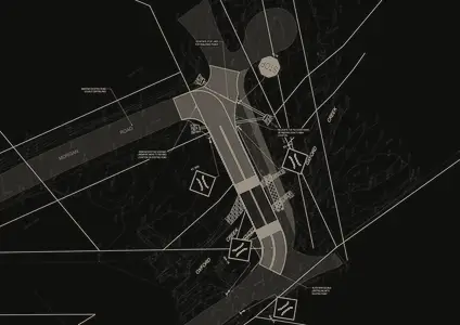
2023Civil and structural
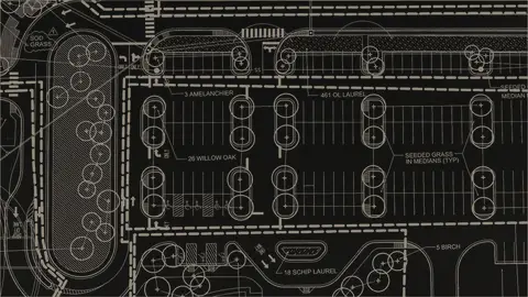
Rethinking a constrained carpark around people, not just bays
A concept for reorganising an existing carpark for better capacity, circulation and pedestrian safety.
Concept design
Concept design
Site planning
Traffic circulation
Stakeholder communication
Read the full case study
Image from the published project record, converted to KEVOS® colours.
The brief
An existing carpark had fixed access points, boundaries and surrounding infrastructure. The concept had to explore better use of the site while balancing vehicle access and circulation, pedestrian movement, accessibility, safety, capacity and future technology.
How the work was approached
Existing site first
The footprint, access points and circulation areas set the constraints for any improvement.
Layout options
Alternative layouts, including a multi-level arrangement for more capacity, were explored at concept level.
Circulation and safety
One-way vehicle circulation and separate pedestrian paths were considered to reduce conflict between people and moving cars, with accessibility built into the layout.
Future features
Landscaping, permeable surfaces and smart-parking ideas such as availability information and booking were explored as concepts.
Outcome
A structured concept for discussing capacity, circulation, pedestrian movement and future features.
Why it mattersThe same thinking applies inside a factory, where flow, access and safety compete for limited floor space.
Further structural, civil, traffic, drainage, planning and regulatory engineering would be needed before construction.
2022Civil and structural
A home extension documented for the CDC fast-track pathway
Residential extension and deck for CDC approval
Private residential client · Residential · NSW
Drawings for a residential extension and outdoor deck, prepared for the Complying Development Certificate (CDC) process.
Documentation delivered
Requirements definition
Compliance awareness
CAD documentation
Change management
Read the full case study
Image from the published project record, converted to KEVOS® colours.
The brief
The owner wanted to extend the house and add an outdoor deck. The proposal had to fit the existing building, levels and boundaries, and meet the requirements of the Complying Development Certificate pathway, so the design could not be shaped by preference alone.
How the work was approached
Clarify the goal
A general wish to “extend the house” was turned into clear requirements for spaces, access and the outdoor area.
Existing conditions
The existing building and site were documented accurately as the baseline for the proposal.
Coordinated design
Layouts, plans, elevations and structural information were developed consistently, with CDC requirements shaping the design.
Ready for the certifier
Documentation was prepared for private certification and revised as feedback arrived, keeping every sheet consistent.
Outcome
A coordinated documentation set supporting the approval and certification process.
Why it mattersDesigning to the approval pathway from the start avoids redesign after review.
Engineering certification and statutory approval remained with registered professionals.
2022Defence and transport
Moving awkward defence components through a tight paint line
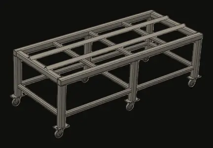
Horizontal paint-line trolley
EPTEC · Defence and industrial maintenance
A heavy-duty trolley for moving large, irregular components through a paint line with limited floor space.
Paused by client
Materials handling
Structural design
Workflow improvement
Safety by design
Read the full case study
Image from the published project record, converted to KEVOS® colours.
The brief
Large, irregular components had to move between preparation, painting and other production stages, and the existing arrangement made handling and floor-space use difficult. The trolley had to carry heavy, uneven loads, stay stable and manoeuvrable, and keep the component accessible for coating.
How the work was approached
Workflow first
How components entered the process, were loaded, accessed and moved between work areas was reviewed to turn production problems into design requirements.
Rigid welded frame
A braced, welded RHS steel frame of about 1.5 m × 0.6 m was developed to resist twisting under uneven loads.
Load path to the floor
Castors in the approximate 200–300 kg rating range were considered, with the load path traced from component to frame, castors and floor.
Open deck and options
An open deck improved coating access, and options such as adjustable supports, rotating platforms and stackable frames were explored for future flexibility.
Outcome
A developed concept for better component handling and floor-space use. The client paused the project for budget reasons before fabrication.
Why it mattersSimple, well-designed handling equipment can remove a bottleneck without a new line.
Any fabricated version would need detailed risk assessment and load verification before use.
2022Defence and transport
One modular support system instead of a fixture for every part
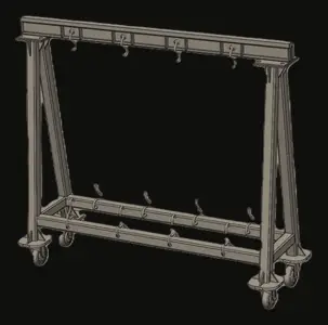
Modular girder system for painting large components
A configurable girder system that holds large components securely while leaving operators access for preparation, coating and inspection.
Design developed
Modular equipment
Large-component handling
Operator-centred design
Workflow improvement
Read the full case study
Image from the published project record, converted to KEVOS® colours.
The brief
Large components needed stable support during preparation, painting and inspection without blocking the surfaces being worked on. A dedicated fixture for each component would have added cost, storage and lead time every time a new part arrived.
How the work was approached
Production questions first
Which surfaces must stay accessible, where parts can safely be supported, practical working heights and how operators move around the job became design inputs.
Modular girder framework
A fabricated girder system with identifiable modules and connection points could be configured for different component sizes.
Load path and stability
Load distribution, support spacing, uneven loading and centre of gravity were considered from component to floor.
Made to fabricate
Standard materials, repeatable elements and practical welding and assembly kept the system simple to build, change and maintain.
Outcome
A developed modular concept showing how one common platform could serve different production requirements in the paint process.
Why it mattersReusable equipment supports change instead of resisting it.
Working-load limits and configurations would be verified before implementation.
Illustrative
2021–2024Window and door hardware
A chainwinder held for a shared design change, then approved on a new tool
Bradnam’s chainwinder
Alchin Long Group · Bradnam’s · Window and door hardware · Sydney, NSW
A chainwinder for Bradnam’s, refined through two prototype reviews, held while a related Doric chainwinder was modified, then completed on a new tool and approved by the customer in November 2024.
Customer approved
Mechanism design
Dependency management
Tooling and OTS
Customer approval
Read the full case study
Illustrative
Illustrative KEVOS® visual. Not an image of the actual project, product, drawing or CAD.
Employment contextProduct-development experience of the founder of KEVOS®, gained while employed by Alchin Long Group as Design Drafter and Product Development (May 2018 to October 2024). It is professional track record, not a KEVOS® client engagement.
The brief
Bradnam’s needed a chainwinder for its windows. The concept was approved quickly and two working prototypes were reviewed in 2022, but the program shared a design dependency with the Doric DS1W chainwinder: its tooling and testing could not be finished until the DS1W cover modifications were complete. When they were, a new tool was ordered, and the product was tested and approved on it.
Objectives
Develop a chainwinder for Bradnam’s windows
Refine it through two prototype reviews
Carry the shared DS1W design change into the tooling
Reach customer approval on production tooling
Role in the work
As Design Drafter and Product Development, the founder’s contribution covered:
Rapid CAD modelling and 3D-printed prototypes
Detailed CAD models and CNC working prototypes
Technical drawings and bills of materials
Tooling quotations and tooling coordination
Off-tool sample testing and tooling corrections
Final testing and samples for customer approval
How the work was approached
Concept approved fast
The brief, rapid CAD models, 3D-printed prototypes and prototype approval were completed between December 2021 and January 2022.
Two prototype reviews
A detailed CAD model and CNC working prototype were reviewed in April 2022, and a second prototype in June and July 2022.
Tooling package
The tooling quotation was reviewed and the tooling and testing plan approved in July 2023, with drawings and the BOM completed by September.
Held for a shared change
Completion of tooling and testing was held until the DS1W cover modifications were finished in August 2024.
New tool and approval
A new tool was ordered and made between August and October 2024, followed by final testing, customer approval in November 2024 and a further round of off-tool testing.
CNC working prototype, two prototype reviews, CAD approval and supplier selection
Apr–Sep 2023Tooling quotation
Quotation and review, tooling and testing plan approved, drawings and BOM
Jul 2023–Nov 2024Tooling and testing
Tooling, off-tool testing, hold for DS1W cover changes, new tool, final testing, customer approval
Challenges and how they were handled
A dependency on another product’s design change.
The remaining tooling work was sequenced behind the DS1W cover modifications, and a new tool was ordered once they were complete.
Feedback from the first working prototype.
A second prototype was built and reviewed within weeks, before the tooling package was approved.
Testing and validation
Two prototype reviews, off-tool sample testing on the original tool, then final testing on the new tool before customer approval in November 2024.
Outcome
Bradnam’s approved the chainwinder in November 2024. The project schedule ends at customer approval and the production meeting, so production release is not claimed here.
Why it mattersRelated products move faster when a shared design change is sequenced deliberately instead of worked around.
In the company’s development process, briefs, prototype approval and customer approval sat with product management; quotation review, ordering and freight sat with supply; and final testing was shared with quality. Dates come from the project schedule. Drawings, CAD models, tooling details, supplier information and internal project records are not shown.
Illustrative
2021–2024Window and door hardware
One chainwinder, two dependencies, approved once both were settled
R5.6 chainwinder
Alchin Long Group · Window and door hardware · Sydney, NSW
A chainwinder for the R5.6 program, prototyped and tooled in 2021–2023, held until the DS1W cover changes and the Bradnam’s program were complete, then corrected, tested and approved by the customer in November 2024.
Customer approved
Mechanism design
Dependency management
Tooling and OTS
Customer approval
Read the full case study
Illustrative
Illustrative KEVOS® visual. Not an image of the actual project, product, drawing or CAD.
Employment contextProduct-development experience of the founder of KEVOS®, gained while employed by Alchin Long Group as Design Drafter and Product Development (May 2018 to October 2024). It is professional track record, not a KEVOS® client engagement.
The brief
The R5.6 chainwinder was developed alongside other chainwinder programs that shared design decisions. Its tooling was made by April 2023, but its schedule records two holds: first until the DS1W cover modifications and the Bradnam’s program were complete, then until the DS1W cover modifications were finished. Only then could the final tooling corrections, testing and customer approval go ahead.
Objectives
Develop a chainwinder for the R5.6 program
Reach CAD approval through a working prototype and customer review
Coordinate tooling with the related DS1W and Bradnam’s programs
Complete corrections, testing and customer approval
Role in the work
As Design Drafter and Product Development, the founder’s contribution covered:
Rapid CAD modelling and 3D-printed prototypes
Detailed CAD models and CNC working prototypes
Technical drawings and bills of materials
Tooling quotations and tooling coordination
Off-tool sample testing and tooling corrections
Final testing and samples for customer approval
How the work was approached
Concept
The brief, rapid CAD models, 3D-printed prototypes and prototype approval were completed between June and July 2021.
Working prototype and customer review
Detailed CAD and the CNC working prototype were developed through to July 2022, followed by customer review and CAD approval in August 2022.
Tooling package
Drawings, the BOM and the tooling quotation were completed and approved between April and June 2022, and tooling was made by April 2023.
First off-tool round
Off-tool samples were tested between April and June 2023.
Sequenced behind related programs
The remaining work was held until the DS1W cover modifications and the Bradnam’s program were complete. Tooling corrections followed from August to October 2024.
Approval
A second round of off-tool testing, final testing and customer approval were completed in November 2024.
Detailed CAD, CNC working prototype, customer review, CAD approval
Apr–Jun 2022Tooling quotation
Drawings and BOM, quotation, review and approval
Jul 2022–Nov 2024Tooling and testing
Tooling, off-tool testing, holds for DS1W and Bradnam’s, corrections, second off-tool round, final testing, customer approval
Challenges and how they were handled
Two overlapping holds on related programs.
The schedule kept both dependencies visible, and tooling corrections started as soon as the DS1W cover changes were complete.
Testing and validation
Customer review of the working prototype, two rounds of off-tool testing around the tooling corrections, and final testing before customer approval in November 2024.
Outcome
The customer approved the R5.6 chainwinder in November 2024. The project schedule ends at customer approval, so production release is not claimed here.
Why it mattersMaking the dependencies between products visible is what lets related programs finish in the right order.
In the company’s development process, briefs, prototype approval and customer approval sat with product management; quotation review, ordering and freight sat with supply; and final testing was shared with quality. Dates come from the project schedule. Drawings, CAD models, tooling details, supplier information and internal project records are not shown.
Illustrative
2021–2024Window and door hardwareFeatured
A double-hung push lock that waited for its customer, then went to production
Wideline Ascend double-hung push lock
Alchin Long Group · Wideline · Window and door hardware · Sydney, NSW
A push lock for Wideline’s Ascend double-hung window, developed through a customer hold and two prototype rounds, then tooled, tested and released to production in 2024.
Released to production
Lock design
Customer validation
Tooling and OTS
Production release
Read the full case study
Illustrative
Illustrative KEVOS® visual. Not an image of the actual project, product, drawing or CAD.
Employment contextProduct-development experience of the founder of KEVOS®, gained while employed by Alchin Long Group as Design Drafter and Product Development (May 2018 to October 2024). It is professional track record, not a KEVOS® client engagement.
The brief
A double-hung push lock has to fit within the sash and meeting-rail profiles, work at the press of a button and hold the window closed. Wideline needed one for its Ascend double-hung window. The concept prototype was approved in mid-2021, but development then waited more than a year for Wideline’s confirmation, and a second prototype was needed before the customer approved the design.
Objectives
Package a push lock within the double-hung sash and meeting rail
Validate it with the customer through prototype rounds
Tool, test and correct the lock to customer approval
Release it to production with documentation in place
Role in the work
As Design Drafter and Product Development, the founder’s contribution covered:
Rapid CAD modelling and 3D-printed prototypes
Detailed CAD models and CNC working prototypes
Technical drawings and bills of materials
Tooling quotations and tooling coordination
Off-tool sample testing and tooling corrections
Production BOMs, kits and first-stock checks
How the work was approached
Concept approved
The brief, rapid CAD models and 3D-printed prototypes were tested, and the prototype was approved between April and June 2021.
Holding for the customer
Development paused from October 2021 to November 2022 while Wideline confirmed the program. Detailed CAD and the CNC working prototype were completed once it resumed.
Two customer reviews
The customer reviewed the first working prototype in April 2023. A second prototype followed in mid-2023 and was approved in October 2023, with CAD approval and supplier selection straight after.
Tooling package
Technical drawings and the BOM were prepared in June 2023, and the tooling quotation was reviewed and approved in October 2023.
Tooling and testing
Tooling was made between October 2023 and April 2024. Off-tool samples were tested and corrected, and final testing and customer approval were completed in May 2024.
Production release
BOMs, kits and a quality-control document were finalised, production ran through June 2024, and the first stock was checked in July 2024.
CNC working prototype, customer review, second prototype, customer approval
May–Oct 2023Tooling quotation
Drawings and BOM, quotation, review and approval
Oct 2023–May 2024Tooling and testing
Tooling, off-tool testing, corrections, final testing, customer approval
May–Jul 2024Production
BOMs and kits, quality-control document, production, first stock checked
Challenges and how they were handled
More than a year waiting for customer confirmation.
The program held at an approved concept, then moved into detailed design and a working prototype once Wideline confirmed.
Feedback on the first working prototype.
A second prototype was built and approved before tooling began.
Testing and validation
Two customer prototype reviews, off-tool sample testing, tooling corrections and final testing before customer approval in May 2024.
Outcome
Wideline approved the push lock in May 2024. It was released to production, and the first stock was checked in July 2024.
Why it mattersWhen a customer pauses a program, keeping the approved concept intact means it can restart without starting over.
In the company’s development process, briefs, prototype approval and customer approval sat with product management; quotation review, ordering and freight sat with supply; and final testing was shared with quality. Dates come from the project schedule. Drawings, CAD models, tooling details, supplier information and internal project records are not shown.
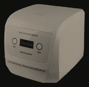
2021Machines and automation
Two kinds of currency, two mechanisms, one compact machine
Banknote and coin sanitising machine
Wink Solutions · Public-facing hygiene equipment
A compact public-facing machine that handles and sanitises both banknotes and coins, developed during COVID-19.
Prototype-ready design
Mechanism design
Product architecture
Design for manufacture
Prototyping
Read the full case study
Image from the published project record, converted to KEVOS® colours.
The brief
The machine had to sanitise both banknotes and coins in a compact public-facing unit. Notes are light, flexible and easily damaged; coins are heavy and rigid and cause impact and wear. One mechanism could not handle both, and supply-chain pressure made component availability a design constraint.
How the work was approached
Dual-path architecture
A controlled roller feed handled banknotes while a robust tumbling arrangement handled coins, with both packaged in one enclosure.
Tuning the note feed
Roller position, guides, clearances and contact pressure were refined to avoid skewing, jamming and creasing.
Iterating in CAD
Autodesk Inventor models were developed through repeated cycles of concept, prototype, review and modification.
Designed for the real world
Part count was reduced, standard and available components preferred, and service access, jam recovery and simple user interaction designed in.
Outcome
The idea progressed to a developed mechanical design ready for further prototyping and manufacturing development, integrating two very different handling mechanisms in one compact machine.
Why it mattersDesigning around available parts kept the product buildable during supply-chain disruption.
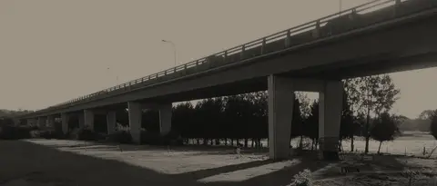
2021Civil and structural
Mapping a bridge’s defects so repairs land in the right place
Macarthur Cowpasture bridge defect survey and repairs
EPTEC (project interface) · Government infrastructure · NSW
Defect mapping, survey drawings and concrete-repair documentation for a bridge rehabilitation.
Documentation delivered
Defect mapping
Repair coordination
Project closeout
Quality assurance
Read the full case study
Image from the published project record, converted to KEVOS® colours.
The brief
The bridge did not need redesigning. It needed its existing defects captured accurately and turned into drawings that could guide repair planning, site work and project closeout. Deterioration, cracking and repair zones had to be located and documented without ambiguity.
How the work was approached
Existing condition recorded
Bridge areas needing attention were transferred into controlled drawings tied to their structural locations.
Defects mapped
Defect location, extent, repair boundaries, dimensions and references were shown so engineers and site teams read them the same way.
What is wrong, and what to do
Defect information and repair intent were kept aligned, so a change to one updated the other.
Records for the future
The package was maintained as a traceable record supporting closeout, quality, audits and future maintenance.
Outcome
A structured technical record supporting the concrete repairs and the bridge’s asset records.
Why it mattersAccurate condition records make repairs easier to price, deliver and verify.
Engineering assessment, structural certification and approval remained with the authorised engineers.
Illustrative
2020–2023Window and door hardware
A MKII lock handle, approved on its second prototype
DS776 and DS777 MKII lock handles
Alchin Long Group · Window and door hardware · Sydney, NSW
A MKII revision of the DS776 and DS777 lock handles, developed through two prototype rounds with customer review, then tooled, corrected and released to production in 2023.
Released to production
Product revision
Customer prototype review
Tooling and OTS
Production release
Read the full case study
Illustrative
Illustrative KEVOS® visual. Not an image of the actual project, product, drawing or CAD.
Employment contextProduct-development experience of the founder of KEVOS®, gained while employed by Alchin Long Group as Design Drafter and Product Development (May 2018 to October 2024). It is professional track record, not a KEVOS® client engagement.
The brief
Revising an established product means every change has to earn its place and be proven before it reaches the customer. The DS776 and DS777 lock handles were revised through a long brief and concept stage, then two prototype rounds reviewed with the customer, before tooling, off-tool testing and corrections. The schedule ran tooling preparation alongside the final prototype rounds to keep the program moving.
Objectives
Define the MKII revision and test it early with 3D-printed models
Reach customer approval through prototype review
Tool the revised parts and correct them against off-tool samples
Release the revised handles with production documentation in place
Role in the work
As Design Drafter and Product Development, the founder’s contribution covered:
Rapid CAD modelling and 3D-printed prototypes
Detailed CAD models and CNC working prototypes
Technical drawings and bills of materials
Tooling quotations and tooling coordination
Off-tool sample testing and tooling corrections
Production BOMs, kits and first-stock checks
How the work was approached
Brief to concept
The brief was defined, then rapid CAD models and 3D-printed parts were tested until the prototype was approved in February 2023.
First prototype, customer review
A detailed CAD model and CNC working prototype went to the customer for review in March 2023.
Second prototype, approved
The feedback went into a second prototype, which the customer approved in early April 2023, followed by CAD approval and supplier selection.
Tooling in parallel
Drawings, the BOM and the tooling quotation were completed in December 2022, so tooling could proceed alongside the prototype rounds.
Corrections and final testing
Off-tool samples were tested in March 2023 and the tooling was corrected through to June, with final testing and customer approval in July.
Release
BOMs, kits and a quality-control document were finalised, production ran in September 2023, and the first stock was checked in October.
CNC working prototype, customer review, second prototype, customer approval
Dec 2022–Jul 2023Tooling and testing
Tooling, off-tool testing, corrections to June, final testing, customer approval
Jul–Oct 2023Production
BOMs and kits, quality-control document, production, first stock checked
Challenges and how they were handled
Customer feedback on the first prototype.
The changes were built into a second prototype within weeks, and that prototype was approved.
Keeping tooling on schedule while the design was being confirmed.
Tooling preparation ran in parallel with the prototype rounds, and the off-tool corrections that followed were closed out before final testing.
Testing and validation
Two prototype rounds with customer review, off-tool sample testing, tooling corrections and final testing before customer approval in July 2023.
Outcome
The MKII handles were approved by the customer in July 2023, went into production in September and reached stock in October 2023.
Why it mattersActing on customer feedback while the part is still a prototype costs far less than changing a tool.
In the company’s development process, briefs, prototype approval and customer approval sat with product management; quotation review, ordering and freight sat with supply; and final testing was shared with quality. Dates come from the project schedule. Drawings, CAD models, tooling details, supplier information and internal project records are not shown.
Illustrative
2020–2022Window and door hardwareFeatured
The handle that lifts the sash, designed, tooled and released for Bradnam’s
Bradnam’s double-hung lift handle
Alchin Long Group · Bradnam’s · Window and door hardware · Sydney, NSW
A lift handle for Bradnam’s double-hung windows, taken from brief and 3D-printed prototypes through tooling, an extended correction period and final testing to production in 2022.
Released to production
Window hardware design
Prototype testing
Tooling corrections
Production release
Read the full case study
Illustrative
Illustrative KEVOS® visual. Not an image of the actual project, product, drawing or CAD.
Employment contextProduct-development experience of the founder of KEVOS®, gained while employed by Alchin Long Group as Design Drafter and Product Development (May 2018 to October 2024). It is professional track record, not a KEVOS® client engagement.
The brief
On a double-hung window the lift handle is how people raise the lower sash, so it has to be comfortable to grip, sit neatly on the sash and suit the window profile it is made for. Bradnam’s needed a handle that met those requirements and could be produced consistently from tooling. The program moved quickly through concept and prototypes in 2020, then needed a longer period of tooling corrections and final testing before customer approval.
Objectives
Develop a lift handle to suit the Bradnam’s double-hung window
Prove the design with 3D-printed and CNC prototypes before tooling
Correct the tooling until off-tool parts matched the design
Release to production with BOMs, kits and a quality-control document
Role in the work
As Design Drafter and Product Development, the founder’s contribution covered:
Rapid CAD modelling and 3D-printed prototypes
Detailed CAD models and CNC working prototypes
Technical drawings and bills of materials
Tooling quotations and tooling coordination
Off-tool sample testing and tooling corrections
Production BOMs, kits and first-stock checks
How the work was approached
Concept in weeks
The brief, rapid CAD models, 3D-printed prototypes and prototype approval were completed between July and early August 2020.
Working prototype
A detailed CAD model and CNC working prototype were reviewed, and CAD approval and supplier selection followed in October 2020.
Tooling package
Technical drawings and the BOM supported a tooling quotation, which was reviewed and approved in early 2021, and the tooling was made by May 2021.
Off-tool testing
The first off-tool samples were tested in mid-2021, and tooling corrections continued from October 2021 to May 2022.
Final testing and approval
Final testing with gauges ran in early 2022, and the customer approved the handle in May 2022.
Release
BOMs, kits and a quality-control document were finalised in June 2022, production followed, and the first stock was checked in October 2022.
Detailed CAD, CNC working prototype, review, CAD approval
Oct 2020–Mar 2021Tooling quotation
Drawings and BOM, quotation, review and approval
Mar 2021–Jun 2022Tooling and testing
Tooling, off-tool testing, corrections Oct 2021 to May 2022, final testing, customer approval
Jun–Oct 2022Production
BOMs and kits, quality-control document, production, first stock checked
Challenges and how they were handled
Off-tool parts needed more correction than first planned.
An earlier schedule aimed for stock in February 2022. Tooling corrections ran until May 2022 instead, and the release dates were re-planned around them.
Testing and validation
CNC prototype review before CAD approval, off-tool sample testing, tooling corrections and final testing with gauges before customer approval in May 2022.
Outcome
Bradnam’s approved the lift handle in May 2022. It was released to production, and the first stock was checked in October 2022.
Why it mattersRe-planning around real off-tool results, rather than the original dates, keeps a part from reaching customers before it is right.
In the company’s development process, briefs, prototype approval and customer approval sat with product management; quotation review, ordering and freight sat with supply; and final testing was shared with quality. Dates come from the project schedule. Drawings, CAD models, tooling details, supplier information and internal project records are not shown.
2020Civil and structural
Turning bridge repair requirements into traceable drawings
Alexandria bridge concrete and reinforcement repairs
EPTEC (project interface) · Government infrastructure · Alexandria, NSW
Repair drawings for the concrete and reinforcement rehabilitation of an existing bridge.
Documentation delivered
Civil drafting
Reinforcement detailing
Drawing control
Compliance support
Read the full case study
Image from the published project record, converted to KEVOS® colours.
The brief
An existing bridge needed concrete and reinforcement repairs. Engineering repair requirements had to become clear, controlled drawings that followed government documentation procedures and could be relied on by engineers, contractors and site teams.
How the work was approached
Start from the real structure
Existing geometry, repair locations, extents and the engineering team’s requirements formed the basis of every drawing.
Concrete repair documentation
Each repair area was shown by location, extent, structural reference, dimensions and designation.
Reinforcement repair details
Reinforcement repairs were detailed and tied to their matching concrete repair areas.
Controlled issue
Drawing standards, revision identification, traceability and review processes kept site teams on current information.
Outcome
A coordinated drawing package supporting the concrete and reinforcement repairs on the bridge.
Why it mattersOn existing assets, controlled drawings prevent rework caused by outdated or conflicting information.
Structural assessment, repair-design approval and certification remained with the responsible engineers.
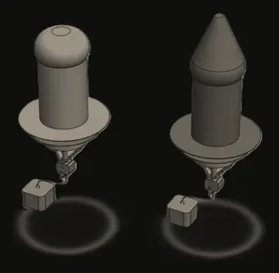
2020Product development
A buoy that rises with the water, with no power needed
Self-adjusting telescopic navigation buoy
Marine product concept · Marine
A passive mechanism that raises a buoy’s visible marker as water levels rise, using buoyancy instead of motors or sensors.
Proof of concept
Concept engineering
Passive mechanisms
Marine design
Simplification
Read the full case study
Image from the published project record, converted to KEVOS® colours.
The brief
Fixed-height buoys become harder to see as water levels rise. The question was whether buoyancy itself could raise the visible marker, avoiding the motors, sensors and electronics that add cost and failure points in a harsh, hard-to-reach marine environment.
How the work was approached
Use the physics
A passive principle was chosen: a change in water level changes buoyancy, which drives telescopic movement and keeps the marker visible.
Telescopic mechanism
Concentric sliding sections were arranged to stay aligned while extending and retracting.
Stability and visibility
Stabilising fins addressed the taller profile, and a high-visibility reflective marker head supported identification.
Built for water
Marine-grade composites were considered for corrosion resistance against water, UV, waves and debris.
Outcome
A defined concept showing how buoyancy could adjust marker height without powered controls. It did not proceed beyond proof of concept after a budget realignment.
Why it mattersFewer systems mean fewer failure modes, which matters most where maintenance access is hardest.
Detailed buoyancy, stability and environmental testing would be needed before any prototype.
Illustrative
2019–2024Window and door hardwareFeatured
Five years from brief to stock: a chainwinder seen all the way through
Doric DS1W chainwinder
Alchin Long Group · Doric · Window and door hardware · Sydney, NSW
A Doric chainwinder for awning windows, taken from design brief and 3D-printed prototypes through a long project hold, tooling, off-tool testing and an extended correction loop to production release in 2024.
Released to production
Mechanism design
Prototype testing
Tooling and OTS
Production release
Read the full case study
Illustrative
Illustrative KEVOS® visual. Not an image of the actual project, product, drawing or CAD.
Employment contextProduct-development experience of the founder of KEVOS®, gained while employed by Alchin Long Group as Design Drafter and Product Development (May 2018 to October 2024). It is professional track record, not a KEVOS® client engagement.
The brief
A chainwinder is the handle-operated mechanism that drives a chain to push an awning sash open and draw it closed. It has to operate smoothly, hold the sash securely and suit the window it is made for, and every part has to come off production tooling consistently. The DS1W began in mid-2019, was placed on hold from early 2020 to late 2021, and then had to be restarted, tooled, tested and corrected before release. Its cover design also became a dependency for other chainwinder programs running at the same time.
Objectives
Turn the design brief into a working chainwinder, proven first with 3D-printed and CNC prototypes
Release drawings, a BOM and a tooling package that suppliers could quote against
Get the off-tool parts right through testing and tooling corrections
Hand production a controlled product: BOMs, kits and a quality-control document
Role in the work
As Design Drafter and Product Development, the founder’s contribution covered:
Rapid CAD modelling and 3D-printed prototypes
Detailed CAD models and CNC working prototypes
Technical drawings and bills of materials
Tooling quotations and tooling coordination
Off-tool sample testing and tooling corrections
Production BOMs, kits and first-stock checks
How the work was approached
Rapid concepts
The brief was turned into CAD concepts and 3D-printed prototypes within weeks, so the mechanism could be handled and tested before tooling was committed.
A working prototype
A detailed CAD model and a first CNC-machined working prototype followed, and the design was reviewed before CAD approval and supplier selection in September 2019.
Restarting after the hold
Drawings and BOM work carried across a project hold that ran from March 2020 to late 2021. The program then resumed at the tooling-quotation stage, and tooling went ahead.
Off-tool testing and corrections
Off-tool samples were tested through the first half of 2023, and the tooling was corrected over the following months until final testing with gauges in May 2024.
A change other programs waited for
Modifications to the DS1W cover were a dependency for other chainwinders in development. The Bradnam’s and R5.6 chainwinder schedules were held until the DS1W cover changes were complete.
Production release
Production preparation ran alongside the final corrections: BOMs and kits were finalised and a quality-control document was written. After customer approval in June 2024, the first production stock was received and checked.
Detailed CAD, first CNC working prototype, review, CAD approval and supplier selection
Sep 2019–Mar 2022Tooling quotation
Drawings and BOM; project on hold Mar 2020 to late 2021; quotation review and approval
Sep 2021–Jun 2024Tooling and testing
Tooling, off-tool testing in 2023, corrections to May 2024, final testing, customer approval
Aug 2023–Jun 2024Production
BOMs and kits, quality-control document, production, first stock checked
Challenges and how they were handled
A hold of almost two years in the middle of development.
The program resumed at the tooling-quotation stage with its drawings and BOM intact, rather than going back to concept.
A long tooling-correction loop after the first off-tool samples.
Samples were tested, the tooling was corrected and parts were re-checked until final testing with gauges was completed in May 2024.
Other chainwinder programs depended on the DS1W cover changes.
Their schedules were sequenced behind the DS1W cover modifications, so the shared change was resolved before their tooling work continued.
Testing and validation
Stage gates throughout: 3D-printed and CNC prototypes were reviewed before CAD approval, off-tool samples were tested before and after tooling corrections, and final testing with gauges was completed before customer approval and release.
Outcome
The DS1W was released to production. Customer approval was recorded in June 2024, and the first production stock was received and checked the same month.
Why it mattersLong programs fail at the hand-offs. Keeping drawings, tooling and testing under control through a hold and a long correction loop is what got this product into production.
In the company’s development process, briefs, prototype approval and customer approval sat with product management; quotation review, ordering and freight sat with supply; and final testing was shared with quality. Dates come from the project schedule. Drawings, CAD models, tooling details, supplier information and internal project records are not shown.
Illustrative
2019–2021Window and door hardware
A keeper made to fit, approved within six months of the brief
AWS 756 side latch keeper
Alchin Long Group · AWS · Window and door hardware · Sydney, NSW
A keeper for an AWS side latch, developed from brief to customer approval in six months, then released to production with BOMs, kits and a quality-control document.
Released to production
Interface design
Design for manufacture
Tooling and OTS
Production release
Read the full case study
Illustrative
Illustrative KEVOS® visual. Not an image of the actual project, product, drawing or CAD.
Employment contextProduct-development experience of the founder of KEVOS®, gained while employed by Alchin Long Group as Design Drafter and Product Development (May 2018 to October 2024). It is professional track record, not a KEVOS® client engagement.
The brief
A keeper only works if the latch finds it every time. It has to suit the latch it receives and the frame it is fixed to, and it has to come off production tooling consistently. The AWS 756 side latch keeper had to do both. Development, tooling and testing were completed by April 2020, and production preparation followed later that year.
Objectives
Develop a keeper to suit the side latch and its frame
Prove the fit with 3D-printed and CNC prototypes
Tool, test and correct the keeper to customer approval
Release it to production with controlled documentation
Role in the work
As Design Drafter and Product Development, the founder’s contribution covered:
Rapid CAD modelling and 3D-printed prototypes
Detailed CAD models and CNC working prototypes
Technical drawings and bills of materials
Tooling quotations and tooling coordination
Off-tool sample testing and tooling corrections
Production BOMs, kits and first-stock checks
How the work was approached
Brief and rapid prototypes
The brief, rapid CAD models and 3D-printed test parts were completed between November and early December 2019.
Tooling package early
Technical drawings, the BOM and the tooling quotation were prepared in parallel and approved in December 2019, so tooling could start straight away.
Working prototype
A detailed CAD model and CNC working prototype were reviewed, with CAD approval and supplier selection in early January 2020.
Off-tool testing and corrections
Off-tool samples were tested in March 2020, the tooling was corrected, and final testing with gauges was completed in April.
Customer approval
The customer approved the keeper at the end of April 2020.
Production release
BOMs and kits were finalised, production ran from December 2020, and a quality-control document was completed before the first stock was checked in March 2021.
Detailed CAD, CNC working prototype, review, CAD approval
Dec 2019–Apr 2020Tooling and testing
Tooling, off-tool testing, corrections, final testing, customer approval
Oct 2020–Mar 2021Production
BOMs and kits, production, quality-control document, first stock checked
Challenges and how they were handled
Getting to an approved part quickly.
The tooling package was prepared alongside the prototypes instead of after them, so tooling started in December 2019.
Testing and validation
CNC prototype review, off-tool sample testing, tooling corrections and final testing with gauges before customer approval in April 2020.
Outcome
AWS approved the keeper in April 2020, and it was released to production, with the first stock checked in March 2021.
Why it mattersPreparing the tooling package alongside the prototypes shortens the path from brief to an approved part.
In the company’s development process, briefs, prototype approval and customer approval sat with product management; quotation review, ordering and freight sat with supply; and final testing was shared with quality. Dates come from the project schedule. Drawings, CAD models, tooling details, supplier information and internal project records are not shown.
Illustrative
2019–2020Window and door hardware
A roller taken from concept to stock in fourteen months
DR2210 roller
Alchin Long Group · Window and door hardware · Sydney, NSW
A roller for a sliding system, developed from brief and prototypes through tooling and off-tool testing to production release in December 2020.
Released to production
Component design
CAD assemblies
Tooling and OTS
Production release
Read the full case study
Illustrative
Illustrative KEVOS® visual. Not an image of the actual project, product, drawing or CAD.
Employment contextProduct-development experience of the founder of KEVOS®, gained while employed by Alchin Long Group as Design Drafter and Product Development (May 2018 to October 2024). It is professional track record, not a KEVOS® client engagement.
The brief
A roller carries the weight of a sliding panel along its track, so its geometry, its fit in the mating profiles and its assembly all decide how the panel runs. The DR2210 had to be designed to suit its sliding system and made consistently from production tooling.
Objectives
Design a roller to suit its sliding system and mating profiles
Prove it with 3D-printed and CNC prototypes
Tool, test and correct it through to customer approval
Release it to production with documentation in place
Role in the work
As Design Drafter and Product Development, the founder’s contribution covered:
Rapid CAD modelling and 3D-printed prototypes
Detailed CAD models and CNC working prototypes
Technical drawings and bills of materials
Tooling quotations and tooling coordination
Off-tool sample testing and tooling corrections
Production BOMs, kits and first-stock checks
How the work was approached
Concept and prototypes
The brief, rapid CAD models and 3D-printed test parts were completed in November and early December 2019, followed by a detailed CAD model and CNC working prototype.
Review and approval
The first prototype was reviewed, and CAD approval and supplier selection were completed in January 2020.
Tooling package
Technical drawings and the BOM were prepared in July 2020, and the tooling quotation was reviewed and approved in August.
Tooling, testing and corrections
Tooling was made from late August, corrections were made in October, and final testing and customer approval were completed in November 2020.
Production in parallel
BOMs, kits and a quality-control document were prepared while the tooling was finalised, so production and first stock followed in December 2020.
Detailed CAD, CNC working prototype, review, CAD approval
Jul–Aug 2020Tooling quotation
Drawings and BOM, quotation, review and approval
Aug–Dec 2020Tooling and testing
Tooling, corrections in October, final testing, customer approval in November, off-tool testing
Sep–Dec 2020Production
BOMs and kits, quality-control document, production, first stock checked
Challenges and how they were handled
A six-month gap between design approval and the tooling package.
Once the tooling package was underway, tooling, testing and production preparation were overlapped, with checks kept between them, so the roller still reached stock by December 2020.
Testing and validation
CNC prototype review, off-tool sample testing, tooling corrections and final testing before customer approval in November 2020.
Outcome
The DR2210 was approved by the customer in November 2020 and released to production, with the first stock checked in December 2020.
Why it mattersOverlapping tooling, testing and production preparation, with clear checks between them, keeps a program on time without skipping a step.
In the company’s development process, briefs, prototype approval and customer approval sat with product management; quotation review, ordering and freight sat with supply; and final testing was shared with quality. Dates come from the project schedule. Drawings, CAD models, tooling details, supplier information and internal project records are not shown.
Illustrative
2019–2020Window and door hardware
Brief to stock in eight months for the New Zealand market
Doric NZ DS209 keeper
Alchin Long Group · Doric NZ · Window and door hardware · Sydney, NSW
A keeper for the Doric New Zealand range, developed, tooled, tested and released to production between May 2019 and January 2020.
Released to production
Interface design
Rapid prototyping
Tooling and OTS
Production release
Read the full case study
Illustrative
Illustrative KEVOS® visual. Not an image of the actual project, product, drawing or CAD.
Employment contextProduct-development experience of the founder of KEVOS®, gained while employed by Alchin Long Group as Design Drafter and Product Development (May 2018 to October 2024). It is professional track record, not a KEVOS® client engagement.
The brief
A keeper has to line up with the locking element it receives, hold it securely and come off tooling consistently. The DS209 was needed for the Doric New Zealand range. Tooling started almost as soon as the prototype was approved, so the whole lifecycle from brief to stock took about eight months.
Objectives
Develop a keeper to suit the New Zealand application
Move from brief to tooling quickly, with prototypes reviewed on the way
Tool, test and correct it to customer approval
Release it with production documentation
Role in the work
As Design Drafter and Product Development, the founder’s contribution covered:
Rapid CAD modelling and 3D-printed prototypes
Detailed CAD models and CNC working prototypes
Technical drawings and bills of materials
Tooling quotations and tooling coordination
Off-tool sample testing and tooling corrections
Production BOMs, kits and first-stock checks
How the work was approached
A fast concept
The brief, rapid CAD model, 3D-printed test part and prototype approval were completed in one week in May 2019.
Tooling started early
Drawings, the BOM and the tooling quotation were completed in May, and tooling began while the CNC working prototype was still being reviewed.
Off-tool testing
Off-tool samples were tested in September 2019, corrected and given final testing with gauges.
Approval and release
The customer approved the keeper in October 2019. BOMs, kits and a quality-control document were then finalised, production ran through to December, and the first stock was checked in January 2020.
Development path
May 2019Concept
Brief, rapid CAD, 3D-printed test part and prototype approval in one week
May 2019Tooling quotation
Drawings and BOM, quotation and approval
May–Jun 2019Development
Detailed CAD, CNC working prototype, review, CAD approval
May–Oct 2019Tooling and testing
Tooling, off-tool testing in September, corrections, final testing, customer approval
Oct 2019–Jan 2020Production
BOMs and kits, quality-control document, production, first stock checked
Challenges and how they were handled
A short program with tooling started early.
Prototype review and tooling ran in parallel, and the off-tool test and correction round in September confirmed the part before approval.
Testing and validation
CNC prototype review, off-tool sample testing, tooling corrections and final testing with gauges before customer approval in October 2019.
Outcome
The DS209 keeper was approved in October 2019 and released to production, with the first stock checked in January 2020, about eight months after the brief.
Why it mattersRunning tooling in parallel with prototype review is how a straightforward part reaches stock in months rather than years.
In the company’s development process, briefs, prototype approval and customer approval sat with product management; quotation review, ordering and freight sat with supply; and final testing was shared with quality. Dates come from the project schedule. Drawings, CAD models, tooling details, supplier information and internal project records are not shown.
2019Machines and automation
From evolving concept to a machine that makes coils
Precision helical coiling machine
RoboHelix Manufacturing · Automotive and electronics
Parametric models and a full manufacturing drawing package for a machine that produces fine-wire coils.
In operation
Precision machinery
SolidWorks
Tolerancing
Manufacturing drawings
Read the full case study
Image from the published project record, converted to KEVOS® colours.
The brief
The machine concept was still developing, yet fabricators, machinists and assemblers needed precise, consistent information to build it. In a coiling machine, small dimensional differences affect both performance and the quality of the coils it produces.
How the work was approached
Parametric models
SolidWorks models controlled dimensions and relationships so the design could change without losing consistency.
Precise helical geometry
Diameter, pitch, curvature, position and orientation of the coiling elements were modelled accurately.
Drawings suppliers can follow
Manufacturing drawings to ISO 128 conventions carried tolerances, materials, finishes and machining and welding notes, with tolerances set by function rather than habit.
Checked before release
Drawings passed a staged review of self-check, peer review and engineering sign-off, with revisions controlled as the machine evolved.
Outcome
The manufacturing package supported fabrication and assembly, and the machine went into operation producing helical coils.
Why it mattersClear, checked drawings let any capable supplier make the part right without guesswork.
2019Defence and transport
Fitting a working kitchen into a train cabin
Train cabin kitchen systems integration
Velocity Melbourne Trains · Rail and transport · Melbourne, VIC
A compact kitchen and equipment area integrating appliances, electrical, fluid services and sheet metal within a train cabin.
Design delivered
Systems integration
Packaging
Sheet metal
Serviceability
Read the full case study
Image from the published project record, converted to KEVOS® colours.
The brief
Appliances, electrical equipment, fluid services, cabinets and service access all had to fit inside a fixed train-cabin envelope. In a vehicle the space cannot grow, so every routing and mounting decision affected something else.
How the work was approached
Coordinated in 3D
A 3D layout checked appliance positions, cabinet geometry and cable and fluid routes at every level, not just in plan.
Services and interfaces
Electrical layout and fluid routing were coordinated around the equipment and around each other.
Multi-function sheet metal
Cabinets and enclosures were redesigned so panels provided support, mounting, cable management and access in one part.
Serviceable and installable
Access panels, removal paths and how assemblies would enter the vehicle were designed in from the start.
Outcome
Coordinated engineering information for integrating kitchen equipment and services into a constrained cabin.
Why it mattersSolving clashes in the model is far cheaper than discovering them during installation.
Electrical calculations, rail certification and compliance approval remained with the responsible disciplines.
2018Civil and structural
A high-load mezzanine designed into an existing Sydney building
Commercial mezzanine level
6 O’Connell St, Sydney · Commercial structures · Sydney, NSW
A 3D structural model and fabrication drawings for a new mezzanine inside an existing commercial building.
Documentation delivered
3D structural modelling
Fabrication documentation
Constructability
Existing-building integration
Read the full case study
Image from the published project record, converted to KEVOS® colours.
The brief
A new mezzanine had to fit within an existing commercial building, working around columns, walls, floor levels, access routes and services. Every member had to be fabricated, brought into the building and installed in a practical sequence.
How the work was approached
Existing building first
The structure was developed from the building’s fixed geometry, interfaces and constraints.
3D structural model
Beams, columns, floor framing, edges and connections were coordinated in 3D to catch interferences early.
Fabrication-ready detail
Members and connections were detailed for cutting, drilling, welding, transport and assembly, using standard sections.
Buildable sequence
Access into the building and the installation sequence were considered so every connection could be reached.
Outcome
A coordinated model and fabrication package linking design intent to manufacture and installation.
Why it mattersA structure is not fully designed until there is a practical way to build it.
Structural calculations, building certification and final engineering approval remained with qualified professionals.
2014–2016Product development
Mass customisation: a different device for every patient
Patient-specific sleep apnoea mouthpieces
Oventus · Medical devices and sleep health
Digital design of oral devices shaped to each patient’s anatomy from 3D scan data.
Design delivered
Mass customisation
3D surface modelling
Digital manufacturing
Medical products
Read the full case study
Image from the published project record, converted to KEVOS® colours.
The brief
Every device had to match an individual patient’s oral anatomy, captured as 3D scan data. The challenge was to handle that variation without losing control of the product design, so each unique device still came from a consistent, repeatable process.
How the work was approached
From scan to geometry
3D oral scan data was interpreted and converted into accurate product geometry, working with organic surfaces rather than simple engineering features.
Standardise the process
A repeatable digital workflow handled patient variation within a controlled product architecture.
Designed for digital manufacture
Geometry continuity, surface quality and data integrity were maintained so each model could be manufactured reliably.
Clinical requirements translated
Requirements from Oventus product and clinical stakeholders were turned into controlled digital geometry.
Outcome
Supported a digital design and manufacturing workflow for patient-specific oral sleep devices.
Why it mattersVariable input plus a controlled process gives consistent output: the core of mass customisation.
Clinical decisions, medical validation and regulatory approval remained with qualified clinical and regulatory professionals.
2013Machines and automation
Depositing machines built for 35–40 trays a minute
Mogul line depositing machinery
NID Pty Ltd (engineering partner) · Food, pharmaceutical and cosmetics production
Special-purpose depositing machines for high-volume production lines, including a swing-hopper depositor.
Machines built
Special-purpose machinery
Automation
Hygienic design
Machine building
Read the full case study
Image from the published project record, converted to KEVOS® colours.
The brief
High-volume mogul lines need depositing equipment that repeats the same action accurately over long runs. Each machine had to be engineered around a specific product, production rate, hygiene requirement and customer, for organisations including Nature’s Product, Tigerbrands, Pharmavite, Sweetcandy, Santacruz, Church and Vite, and Interpack.
How the work was approached
Process before machine
Product, process and required motion defined the machine architecture, rather than adapting the process to a standard machine.
Reliable at speed
At around 35–40 trays per minute, cycle time, timing, durability and tray positioning were designed for consistency.
Swing hopper and manifolds
A swing-hopper depositor and volumetric depositor manifolds were developed to distribute product evenly across positions.
Hygiene, assembly and commissioning
Cleaning access, materials and component removal were designed in, and development continued through assembly, integration and commissioning.
Outcome
A number of special-purpose machines were built for food, pharmaceutical and cosmetics production, including depositors designed for about 35–40 trays per minute.
Why it mattersSmall inconsistencies repeated thousands of times become big production problems, so they are designed out early.
2011–2012Heavy industry and miningFeatured
Packing a mobile manufacturing plant onto a truck
Bulk Master Series 7 mobile manufacturing unit
Orica · Mining equipment
Mechanical design for modifications to a truck-mounted mobile manufacturing unit used at mine sites.
Design delivered
Mobile equipment
Systems integration
Sheet metal
Design for manufacture
Read the full case study
Image from the published project record, converted to KEVOS® colours.
The brief
The Bulk Master Series 7 combines tanks, hose reels, process pipework and equipment on one heavy vehicle. Every addition had to fit a fixed truck envelope while respecting weight, chassis interfaces, manufacture, maintenance, operator access and mine-site conditions.
How the work was approached
The truck as one system
Each component’s position was judged by its effect on weight distribution, structure, routing, access and neighbouring equipment.
Tanks, reels and pipework
Fuel tanks, hose-reel systems and chemical pipework were designed together with their mounting, servicing and operator interaction.
Engineered sheet metal
More functions were built into formed sheet-metal parts, simplifying assemblies and saving weight.
Controlled change
Modifications to the existing platform were controlled from design change through updated drawings to manufacture.
Outcome
Supported development of the next generation of Orica’s Bulk Master mobile manufacturing equipment.
Why it mattersOn mobile equipment every kilogram and millimetre counts, so integration decisions are made for the whole vehicle.
Formal safety assessment, regulatory compliance and final engineering approval remained with the authorised engineers.
2011Heavy industry and mining
Step-by-step sequences for a blast furnace shutdown
Blast furnace shutdown maintenance documentation
OneSteel Whyalla · Steel production · Whyalla, SA
Drawings and step-by-step work sequences for refractory brickwork and liner replacement during a blast furnace maintenance program.
Documentation delivered
Shutdown maintenance
Work sequencing
Structural drafting
High-risk environments
Read the full case study
Image from the published project record, converted to KEVOS® colours.
The brief
Refractory brickwork and furnace liners wear under extreme heat and are replaced during a controlled shutdown, where every delay affects the return to production. Site teams needed to know not just the finished state, but what came out first, what went in next and what depended on what.
How the work was approached
Existing condition
The existing furnace arrangement and work areas were interpreted to define what would be removed, retained and replaced.
Sequential instructions
2D sequential drawings showed the work progressing through access, removal, inspection, preparation, replacement and verification.
Access and constructability
Access, working space, material delivery and activities that could block each other were reflected in the sequence.
Controlled revisions
As components were exposed and conditions changed, drawings were revised under control so every team worked from current information.
Outcome
Technical documentation supporting a major blast-furnace maintenance program.
Why it mattersIn a shutdown, unclear information costs the most exactly when time is shortest.
Furnace engineering, refractory specification, shutdown control and approval remained with the responsible specialists.
2011Heavy industry and mining
Making structure and pipework share a crowded coke plant
Coke Plant No. 5 structural and piping coordination
BlueScope Steel · Steel production
Structural and piping documentation for an operating coke plant, coordinated so new work fitted the existing plant.
Documentation delivered
Plant design
Piping coordination
Clash detection
Constructability
Read the full case study
Image from the published project record, converted to KEVOS® colours.
The brief
In an operating coke plant, structure, pipework, equipment, platforms and access all compete for the same space. A new support could block a pipe route; a pipe route could block maintenance access. The work had to resolve those interfaces before they reached site.
How the work was approached
Existing plant as the boundary
Existing structures and infrastructure defined where new or modified systems could fit.
Structural documentation
Members, supports, platforms, brackets and connections were documented in relation to the wider plant.
Piping coordination
Pipe routes were developed around structures, equipment, supports, access and adjacent systems, not just the shortest path.
Clashes found early
Pipework, structure, access routes and existing plant were reviewed together, and conflicts resolved or flagged before fabrication.
Outcome
Coordinated multidisciplinary documentation supporting engineering review, fabrication and construction.
Why it mattersMost plant problems live at the interfaces, and they are cheapest to fix on the drawing.
Engineering calculations, process design and certification remained with the responsible engineers.
2011Heavy industry and mining
Conveyors, chutes and crushers designed as one system
Conveyor, transfer chute and crushing plant design
NEPEAN Conveyors · Mining and bulk materials handling
Layouts and documentation for bulk-material handling systems combining conveyors, transfer chutes and crushing equipment.
Documentation delivered
Bulk material handling
Plant layout
Structural coordination
Systems thinking
Read the full case study
Image from the published project record, converted to KEVOS® colours.
The brief
Bulk material has to move reliably from feed to conveyor, through transfer points and crushing, and on to the next process. A problem at any interface, such as poor transfer geometry or blocked access, affects everything downstream.
How the work was approached
System-level layout
Conveyor routing, elevations, transfer locations, drives and supporting structures were laid out around the site and the surrounding plant.
Transfer chutes and crushers
Chute entry and discharge, clearances, wear areas and the equipment around crushers were documented as working interfaces.
Structure and access
Conveyor supports, towers, platforms and walkways were coordinated with maintenance needs such as belt inspection, roller replacement and liner changes.
Clash-free and buildable
Spatial conflicts were identified during design, and documentation supported fabrication, transport and installation.
Outcome
Coordinated documentation for an integrated bulk-material handling plant.
Why it mattersDesigning for maintenance as well as installation keeps a plant running long after commissioning.
Conveyor calculations, bulk-flow analysis and certification remained with the responsible engineers.
2010–2011Heavy industry and miningFeatured
Maintenance drawings that work around an operating steelworks
Coke Plant No. 6 maintenance and upgrade documentation
BlueScope Steel · Steel production
Structural drawings and installation-sequence information for maintenance and upgrade work inside an operating coke plant.
Documentation delivered
Brownfield engineering
Structural drafting
Shutdown planning
Revision control
Read the full case study
Image from the published project record, converted to KEVOS® colours.
The brief
Maintenance and upgrades inside an established coke plant must work around existing structures, equipment, access limits and shutdown windows. Drawings had to show how the plant could be modified, not just the finished arrangement.
How the work was approached
Read the existing plant
Existing drawings and site information were interpreted for geometry, member locations, connections and clearances.
Existing versus proposed
Maintenance drawings showed what was removed, what was new and how it connected.
Installation sequence
2D sequence information answered what comes out first, what needs temporary access and when the new part goes in.
Revision control
When site work revealed differences from historical drawings, changes were carried through fabrication and installation documents.
Outcome
Controlled documentation that supported planning, fabrication and installation of maintenance work.
Why it mattersIn brownfield work the sequence is its own engineering problem, separate from the final design.
Structural calculations, approval and certification remained with the responsible engineers.
Have a project like these?
Send a drawing, photos or a short description. KEVOS® will come back with a clear scope, deliverables and an appropriate next step before any substantial work begins.
Organisation names show where the work took place and do not imply endorsement of KEVOS®. Work carried out while employed, including the Alchin Long Group product-development and capital projects, is the founder’s professional track record, not KEVOS® client work. Product-development dates come from the project schedules, and a product is described as released to production only where its schedule records it. Organisation descriptions are general background. Engineering calculations, certification and statutory approvals remained with the responsible engineers and authorities. Projects that ended at concept or design stage are labelled that way, and visuals marked “Illustrative” are not images of the actual project. Commercial figures and client-confidential information are not shown.
Have work that needs moving forward?
Describe the drawing, project, manufacturing process or technical problem. KEVOS® can help define a practical scope and an appropriate next step.
Welcome to KEVOS®. I can help identify the most relevant engineering, manufacturing, operations or project support for your requirement, explain how engagement works, and guide you to the right next step.
AI-assisted guidance based on published KEVOS® information. For project scope, pricing or availability, request a quote. Please don’t share sensitive information. Privacy